Converging lens direct image. Studying the properties of images obtained using a converging lens
Equipment for laboratory work
1 - meter ruler
2 - lens on a stand
3 - white matte screen
4 - light source
The purpose of the work is to determine the focal length of the lens and construct images of the light source obtained using the lens.
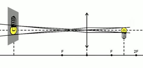
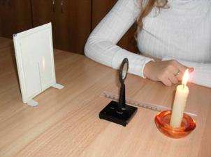
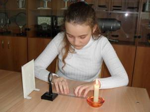
To obtain the focal length, it is necessary to position the light source as far as possible from the lens, and position the screen in such a way that it is convenient to count distances (Fig. 1).
Rice. 1. Layout of equipment for experiment 1
We will move the screen until a clear and clear image is obtained.
You need to turn on the light, take the screen and bring it closer to the lens. We should get a luminous, very bright point. This is the image obtained at the focal point of the lens. The distance between the lens and the screen is the focal length of that lens. It approximately corresponds to 15 centimeters.
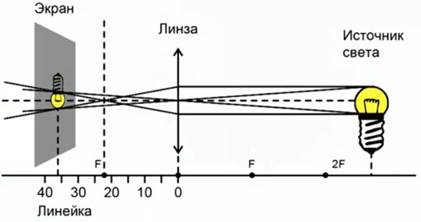
Second experience. Capturing an image when the light source is between focus and double focus.
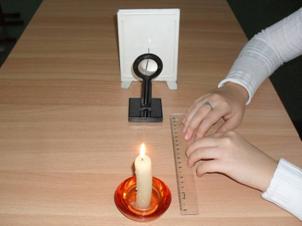
We will place the light source between the focus and double focus of the lens. By positioning the light source in this way, we will get an enlarged inverted image of the light source on the screen (Fig. 2).
Rice. 2. Light source and its images, experiment 2
Third experience. Obtaining an image when the light source is behind the double focus (Fig. 3).
Rice. 3. Light source and its image, experiment 3
We will place the light source behind the double focus. By bringing the screen closer to the lens, we get a clear image of the light source. This image is scaled down and upside down.
We summarize the results of the work in Table 1.
Table 1. Laboratory results
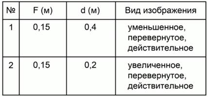
F (m) - focal length, measured in meters.
d (m) - the distance between the object and the lens, measured in meters.
In the conclusion from the laboratory work, it is necessary to note how the image changes depending on where the light source is located.
Conclusion
You have gained practical skills in determining the focal length of a lens, as well as constructing images obtained using a lens.
Bibliography
- Gendenshtein L.E., Kaidalov A.B., Kozhevnikov V.B. /Ed. Orlova V.A., Roizena I.I. Physics 8. - M.: Mnemosyne.
- Peryshkin A.V. Physics 8. - M.: Bustard, 2010.
- Fadeeva A.A., Zasov A.V., Kiselev D.F. Physics 8. - M.: Enlightenment.
- Tepka.ru ().
- Tak-to-ent.net ().
- Fizika.in ().
Homework
Task 1. Construct an image of an object located from a converging lens at a distance and .
Task 2. At what distance from the collecting lens should an object be placed to obtain an image:
a) reduced
b) equal to the subject
c) enlarged (straight and inverted).
Task 3. Can a biconvex lens give a real image of an object?
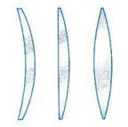
1. The picture shows glass lenses. Which ones are collecting?
A. a, b. B. a, b, c. V. a, c. G. b, g.
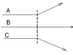 2. What stands in the way of a beam of rays ABC passing through the air?
A. Converging lens.
B. Diverging lens.
C. Plane-parallel glass plate.
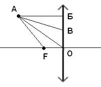 3. To construct an image of point A using a collecting lens, it is convenient to use the following rays:
A. AB, AF only.
B. AB, AF only.
B. Only AB, AO, AF.
4. Find the optical power of a diverging lens with a focal length of 20 cm.
A. 0.05 diopters. B. –5 diopters. B. 5 diopters.
5. An image was obtained using a collecting lens luminous point. What is the focal length of the lens if d=0.5 m, f=1 m?
A. 0.33 m. B. 0.5 m. C. 1.5 m. D. 3 m.
6. Based on the conditions of the previous problem, determine what the magnification of the lens is.
A. 0.33. B. 0.5. V. 1.5. G. 2.
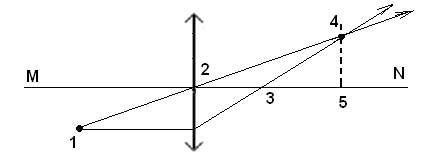
The figure shows the path of light rays through the lens, MN is the main optical axis of the lens.
7. Which of the points marked in the figure is the optical center of the lens?
8. Which of the points marked in the figure is the main focus of the lens?
A. 1. B. 2. C. 3. D. 4. E. 5.
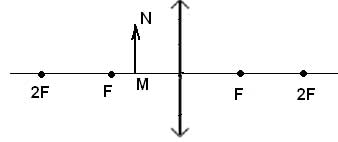
9. The figure shows the position of the main optical axis lens, its main focuses and subject MN. What image of the object will you get?
A. Real, reduced. B. Real, increased. B. Imaginary, reduced. D. Imaginary, enlarged. D. There will be no image.
10. At what distance is an object usually placed in relation to a lens with focal length F in a camera?
A. L>2F. B. F<L<2F. IN. L» F. G. L<F.
Municipal educational budgetary institution
Secondary school No. 13, Sochi
Studying the properties of images obtained using a converging lens
student of class 10A MOBU secondary school No. 13, Sochi
Supervisor:
Physics teacher MOBU Secondary School No. 13, Sochi
Sochi, 2012
0 " style="border-collapse:collapse">
Introduction
Chapter 1. Theoretical foundations of optical lenses
1.1 Concept and types of lenses
1.2 Basic concepts used to describe the path of rays through lenses
1.3 Use of lenses
2.1 Research methodology
2.2 Research results
Conclusion
Literature
Introduction
“There is nothing better in life than your own experience.”
Walter Scott
In everyday life, we often come across lenses, for example, when we use glasses or contact lenses, a magnifying glass, binoculars, a telescope, a microscope or a camera.
Therefore there arises problem, What types of lenses are there and what images can be obtained with their help?
The lack of knowledge on this issue and the desire to study the properties of the images produced by the lenses determined the choice Topics research “Study of the properties of images obtained using a converging lens.”
Object research is a converging lens.
As subject The study consists of images obtained using a converging lens.
Purpose research is to obtain images using a converging lens and study their properties.
To achieve this goal, the following were decided tasks:
· selection of literature on the problem;
· study, analysis, generalization of literature on the problem;
· obtaining images using a converging lens and studying their properties;
· analysis of the results obtained.
Hypothesis research: a converging lens produces virtual and real images.
During the work the following were used methods research:
· Theoretical (study, analysis, synthesis of literature).
· Empirical (observations, conversations, measurements).
· Interpretive (quantitative and qualitative processing of results).
Novelty The work consists of setting up simple experiments to study the properties of images obtained using a converging lens.
Practical significance The work is that the use of the experiments allows us to consider the issue of the properties of images obtained using a converging lens more clearly.
Work structure: the work consists of an introduction, two chapters, a conclusion, a list of references and contains 2 tables, 22 figures.
1. Theoretical foundations of optical lenses
1.1 Concept and types of lenses
The first mention of lenses is found in the ancient Greek play “Clouds” by Aristophanes, where fire was made using convex glass and sunlight. From the works of Pliny the Elder it follows that this method of kindling fire was also known in the Roman Empire. His works describe perhaps the first use of lenses for vision correction: Nero watched gladiatorial fights through a concave emerald to correct myopia. Seneca described the magnifying effect of a glass ball filled with water. The Arab mathematician Alhazen wrote the first significant treatise on optics, describing how the lens of the eye creates an image on the retina. Lenses came into widespread use with the advent of glasses around the 1820s in Italy.
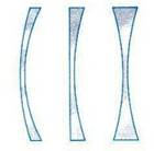
Lens(translated from Latin “lens” - lentil) - a body made of a material that is transparent to optical radiation in a certain wavelength range, limited by convex or concave surfaces (one of the surfaces may be flat). Currently, “aspherical lenses” are also used, the surface shape of which differs from a sphere. Lenses are one of the main elements optical systems. Optical materials such as glass, optical glass, plexiglass (polymethyl methacrylate) are used as lens materials. Lenses for the ultraviolet region of the spectrum are made of quartz, fluorite and lithium fluoride, for the infrared region - from special glass, silicon and cesium iodide. The most common are lenses with spherical surfaces (biconvex, biconcave, menisci), as well as lenses in which one surface is spherical and the other is flat. Less commonly used are lenses with two mutually perpendicular planes of symmetry; their surfaces can be cylindrical or toroidal (spectacle lenses that correct astigmatism of the eye, lenses for anamorphic attachments). There are 2 main types of lenses - converging lenses, in which the middle is thicker than the edges (Fig. 1, Fig. 3) and diverging lenses, in which the edges are thicker than the middle (Fig. 2, Fig. 4 ).
Converging lenses Diffusing lenses
Rice. 1 Fig. 2
Designation of a converging lens Designation of a diverging lens
Rice. 3 Fig. 4
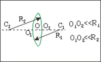
If the thickness of the lens along the optical axis is negligible compared to the radii of curvature of its surfaces, then the lens is called thin (Fig. 5). Points O1 and O2 are so close that the path of the beam inside the lens is infinitely small and there is no spatial displacement of the beam. Therefore, we can assume that the rays experience not two refractions, but one - on the plane passing through the midpoint O.
Thin lens image
Rice. 5
1.2 Basic concepts used to describe the path of rays through lenses
Optical center of the lens - center point O, through which the rays pass without changing direction (Fig. 6, Fig. 7).
Main optical axis – straight line NN passing through the centers of curvature of the spherical surfaces limiting the lens (Fig. 6, Fig. 7).
Focus lenses- point F on the main optical axis, at which the rays (or their continuations) incident on the lens parallel to the main optical axis intersect after refraction (Fig. 6, Fig. 7). Any lens has two focuses - front and back, located on the optical axis on both sides of the lens. In a converging lens, the foci are real, since the rays themselves refracted by the lens intersect at them (Fig. 8). A diverging lens has imaginary foci, since the extensions of the rays refracted by the lens intersect at them (Fig. 9).
A distinctive property of a converging lens is the ability to collect rays incident on its surface at one point located on the other side of the lens. If a luminous point S is placed at a certain distance in front of the collecting lens (Fig. 6), then a ray of light directed along the axis will pass through the lens without refraction, and rays passing not through the center will be refracted towards the optical axis and intersect on it at some point F, which will be the image of point S. This point is called the conjugate focus, or simply focus. If light falls on the lens from a very distant source, the rays of which can be imagined as traveling in a parallel beam, then upon exiting it the rays will refract at a large angle and point F will move on the optical axis closer to the lens. Under these conditions, the point of intersection of the rays emerging from the lens is called the focus F".
Focal length - distance OF from the optical center to its focus (Fig. 6, Fig. 7). Focal length is measured in meters. For a converging lens F > 0, for a diverging lens F< 0.
Focal plane- a plane passing through the main focus of the lens perpendicular to the optical axis NN.
Lens power– the value of D, the reciprocal of the focal length: D = 1/F. For a converging lens D > 0, for a diverging lens D< 0. Единица измерения оптической силы линзы – диоптрия. 1 дптр = 1 м -1.Линзы являются универсальным оптическим элементом большинства оптических систем. Афокальные линзы имеют Ф = 0 (их фокусное расстояние равно бесконечности) - не собирают и не рассеивают световые лучи и используются главным образом в линзовых и зеркально-линзовых объективах как компенсаторы аберраций .
Basic elements of a converging lens http://pandia.ru/text/77/499/images/image008_55.gif" width="613" height="274 src=">
Rice. 7
Path of rays in a collecting lens
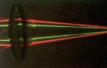
Fig.8
Path of rays in a diverging lens
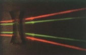
Fig.9
1. 3 Use of lenses
Our eyes are optical instruments. When we look at an object, a lens system located in the front of each eye forms an image of it on the retina, a layer of the fundus of the eye containing approximately 125 million light-sensitive cells. Light hitting the retina causes the cells to send an electrical nerve signal to the brain, allowing us to visually perceive an object. In addition, the eyes have a brightness adjustment system. In bright light, the pupil instinctively constricts, reducing the brightness of the image to an acceptable level. In low light, the pupil dilates, increasing the brightness of the image. .
The lens system of the eye consists of a convex lens, the lens, and a fluid-filled, curved membrane in front of it called the cornea. The cornea provides four-fifths of the entire focusing process. Fine adjustment is carried out by the lens, whose surface curvature is changed by a muscle ring (capsule) located around it. When the eye cannot take the necessary shape, usually due to problems in these muscles, images of visible objects become blurred. The most common vision deficiency is the inability to focus images of individual objects on the retina. If the lens system of the eye is too strong, in other words, if it is very convex, then distant objects will blur, but close ones will produce clear images. People with this disorder are called myopic. If the convexity of the lens is insufficient, then close objects will blur, but images of distant objects will remain clear. People with this type of vision are called farsighted. Both disorders can be corrected by wearing glasses or contact lenses. Nearsighted people wear glasses with concave lenses (thinner in the middle) that allow their eyes to focus on distant objects. Farsighted people wear glasses with convex lenses (thick in the center). Ophthalmology- an important area of application for lenses, without which it is impossible to correct vision defects - myopia, farsightedness, improper accommodation, astigmatism and other diseases. In the field of ophthalmology, soft contact lenses(Fig. 11). Their production is based on the use of materials of a biphasic nature, combining fragments organosilicon or organosilicon polymer silicone and hydrophilic polymer hydrogel. In the late 90s of the 20th century, lenses were created that, thanks to a combination of hydrophilic properties and high oxygen permeability, can be used continuously for 30 days around the clock.
Strong convex lenses are often used as magnifying glasses(Fig. 10). The first magnifying devices were used approximately 2000 years ago. Ancient Greek and Roman documents describe how a round glass vessel filled with water could be used to enlarge objects. Lenses made entirely of glass appeared much later and were probably first used in the 11th century by monks working on manuscripts. At the end of the 13th century, magnifying glasses with low magnification were already used in glasses to correct farsightedness. The technique of making concave lenses to correct myopia was invented only at the beginning of the 15th century.
Using a converging lens as a magnifying glass
 http://pandia.ru/text/77/499/images/image013_50.jpg" width="148" height="147">
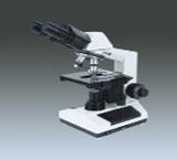
1) magnifying glasses 2) spotting scope 3) microscope
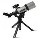
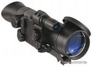
4) telescope 5) optical sight 6) binoculars
 http://pandia.ru/text/77/499/images/image021_27.jpg" width="156 height=124" height="124">
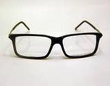
7) glasses 8) contact lenses 9) radar
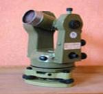
10) camera 11) theodolite 12) video camera
Rice. eleven
Among scientists there is no consensus on the issue of the invention of the telescope: some authors believe that it was invented in the 13th century by the English philosopher and naturalist Roger Bacon, other authors believe that the telescope was invented by Arab scientists.
The telescope, created in 1608 by the Dutch optician Hans Lippershey, attracted the attention of the Italian scientist Galileo Galilei. Within a short time, Galileo improved Lippershey's design and created several pipes with improved characteristics. With their help, he made a number of discoveries, including mountains and valleys on the Moon, as well as the four moons of Jupiter. Galileo's discoveries showed the importance of the telescope, and the type of instrument he used became known as the Galileo telescope. The convex lens of his objective collected light from the observed object. A concave lens The eyepiece deflected light rays in such a way that they created a magnified direct image. The lenses were installed in pipes, one of which (of smaller diameter) slid inside the other. This made it possible to adjust the distance between the lenses while obtaining a clear image. The Galilean telescope works using the principle of refraction (bending) of light and is therefore also known as a refracting telescope. Another type of refracting telescope is characterized by convexity of both lenses. This design produces a magnified but inverted image and is known as an astronomical telescope.
One major problem with early refracting telescopes was a lens defect called chromatic aberration, which caused unwanted colored halos to appear around images. To eliminate this drawback, the English scientist Isaac Newton designed a reflecting telescope in the 1660s. To concentrate light rays and create an image, it uses a concave mirror instead of an objective lens, which does not form colored halos. Flat mirror reflects light into a convex eyepiece lens mounted on the side of the main tube. This type of instrument is known as a Newtonian telescope.
A magnifying glass is sometimes called a simple microscope because it is used for observing small objects. A compound microscope consists of two convex lenses. The objective lens creates a magnified image, which is then magnified again by the eyepiece lens. As in an astronomical telescope, this image is upside down. Many compound microscopes have a set of objective lenses with varying degrees of magnification.
Modern photographic equipment places high demands on image quality. The image produced by a simple lens, due to a number of shortcomings, does not satisfy these requirements. Elimination of most shortcomings is achieved by appropriate selection of a number of lenses into a centered optical system - a lens. Images obtained using simple lenses have various imperfections (aberrations). Aberrations are divided into geometric aberrations (spherical aberrations; coma; astigmatism; distortion; curvature of the image field); chromatic aberrations; diffraction aberrations.
In radio astronomy and radar dielectric lenses are often used to collect the flow of radio waves into the receiving antenna or focus them on the target.
In the design of plutonium nuclear bombs To transform a spherical diverging shock wave from a point source (detonator) into a spherical converging one, lens systems made of explosives with at different speeds detonation (that is, with a different refractive index).
We have carried out an experimental study of the properties of images obtained using a converging lens. The research methodology and results are presented in Chapter 2.
Chapter 2. Experimental study of the properties of images obtained using a converging lens
2.1 Research methodology
The work on studying the properties of images obtained using a converging lens consisted of three stages:
Stage 1. Preparatory. September 2011
Selection and study of literature on the problem.
Stage 2. Practical. October 2011
Study of the properties of images obtained using a converging lens.
Stage 3. Generalizing. November 2011
Generalization of the obtained results.
When conducting the experiment, we used the equipment indicated in Table 1.
Table 1
Equipment used during the study
During the study, we used the following method as a laboratory experiment, the advantages of which are simplicity and clarity. Laboratory studies were carried out on the basis of Municipal Educational Institution Secondary School No. 13 in Sochi.
The following experimental methodology was used:
1. Determination of the focal length and optical power of a collecting lens.
1. Using a converging lens on a stand, a clear, real, inverted, reduced-scale image of the window was obtained on the screen.
2. Using a ruler, the distance from the lens to the window image on the screen was measured - the focal length F of the lens (Fig. 12).
3. Using the calculation formula D = 1/F, the optical power of the collecting lens was determined.
Determining the focal length of a collecting lens
Rice. 12
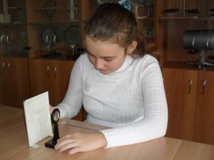
2. Study of the properties of the image obtained using a converging lens in the case when the object is located between the center of the lens and its focus.
1. The converging lens was located above the printed text of the book at a distance of 0< d < F.
2. The resulting image of the text letters was observed using a lens and the properties of the image obtained using a converging lens were studied in the case when the object is located between the center of the lens and its focus (Fig. 13).
Study of the properties of the image obtained using a converging lens in the case when the object is located between the center of the lens and its focus

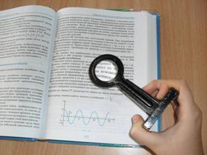
Fig.13
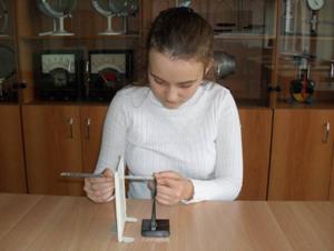
3. Study of the properties of the image obtained using a converging lens in the case when the object is at the focus of the lens.
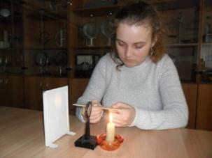
1. The candle was located at a distance F = d from the collecting lens.
2. The resulting image of a candle flame was observed using a lens, and the properties of the image obtained using a converging lens were studied in the case when the object was at the focus of the lens (Fig. 14).
Study of the properties of the image obtained using a converging lens in the case when the object is at the focus of the lens
Rice. 14
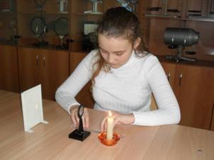
4. Study of the properties of the image obtained using a converging lens in the case when the object is located between the focus of the lens and its double focus.
1. The candle was located at a distance F< d < 2 F от собирающей линзы.
2. The resulting image of a candle flame was observed using a lens and the properties of the image obtained using a converging lens were studied in the case when the object is located between the focus of the lens and its double focus (Fig. 15).
Study of the properties of the image obtained using a converging lens in the case when the object is located between the focus of the lens and its double focus
Rice. 15
4. Study of the properties of the image obtained using a converging lens in the case when the object is in its double focus.
1. The candle was located at a distance d = 2 F from the collecting lens.
2. The resulting image of a candle flame was observed using a lens and the properties of the image obtained using a converging lens were studied in the case when the object was at its double focus (Fig. 16).
Study of the properties of the image obtained using a converging lens in the case when the object is at its double focus
Rice. 16
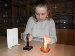
5. Study of the properties of the image obtained using a converging lens in the case when the object is located behind its double focus.
1. The candle was located at a distance d > 2 F from the collecting lens.
2. The resulting image of a candle flame was observed using a lens and the properties of the image obtained using a converging lens were studied in the case when the object is located behind its double focus (Fig. 17).
Study of the properties of the image obtained using a converging lens in the case when the object is located behind its double focus
Rice. 17
2.2 Research results
During the experiment the following were obtained results(Table 2):
table 2
Properties of images obtained using a converging lens
Focal length F, cm | Distance from lens to object d, cm | Image properties |
|
1. Imaginary; 2. enlarged; 3. direct; 4. is on the same side of the lens as the object at a distance F< f < 2 F. |
|||
Absent |
|||
1. Real; 2. enlarged; 3. inverted; |
|||
1. Real; 2. equal in size to the object; 3. inverted; 4. is on the other side of the lens than the object at a distance |
|||
1. Real; 2. reduced; 3. inverted; 4. is on the other side of the lens than the object at a distance F< f < 2 F. |
1. The focal length of the collecting lens is F = 7 cm. The optical power of the collecting lens is D = 1/F = 1/0.07 m = 14.3 diopters.
2. When an object (letter) is between the lens and its focus, its image is enlarged, virtual, direct, located on the same side of the lens as the object at a distance F< f < 2 F; по мере удаления предмета (буквы) на расстоянии F >d > 0 from the lens, its image increases (Fig. 18). Therefore, in everyday life, in order to get a good look at a small object, we bring a collecting lens in a frame close to it, which in this case is called a magnifying glass and gives an enlarged direct image of the object.
Constructing an image obtained using a converging lens in the case when an object is located between the center of the lens and its focus
Rice. 18
3. If it is in the focus of the lens, then its image is absent (Fig. 19). In practice, such an arrangement of the object relative to the lens does not occur.
Lack of image of an object located at the focus of a converging lens
Rice. 19
4. When a light source is between the focus and double focus of a lens, its image becomes real and inverted, magnified, located on the other side of the lens than an object at a distance f > 2F. It decreases as the light source approaches the double focus of the lens (Fig. 20). This arrangement of the object relative to the lens is used in a microscope and projection apparatus.
Construction of an image obtained using a converging lens in the case when an object is located between the focus of the lens and its double focus
Rice. 20
5. The image of the light source located at the double focus of the lens becomes an image equal in size to the light source and is located at the double focus of the lens on the other side of the lens (Fig. 21). In some cases, in practice, such an arrangement of the object relative to the lens occurs.
Construction of an image obtained using a converging lens in the case when the object is at its double focus
http://pandia.ru/text/77/499/images/image039_23.gif" width="641" height="211 src=">
Rice. 22
This arrangement of the object relative to the lens is used in an optical device such as a camera.
Thus, our hypothesis research that a converging lens produces virtual and real images, fair.
Conclusion
Analysis of the obtained literature and experimental data allows us to conclude that:
1. A lens is a body made of a material that is transparent to optical radiation in a certain wavelength range, limited by convex or concave surfaces (one of the surfaces may be flat).
2. Lenses are one of the main elements of optical systems. Optical materials such as glass, optical glass, and plexiglass are used as lens materials. Lenses for the ultraviolet region of the spectrum are made of quartz, fluorite and lithium fluoride, for the infrared region - from special glass, silicon and cesium iodide.
3. There are 2 main types of lenses - converging lenses, in which the middle is thicker than the edges, and diverging lenses, in which the edges are thicker than the middle. .
4. If the thickness of the lens along the optical axis is negligible compared to the radii of curvature of its surfaces, then the lens is called thin.
5. The optical center of a lens is the central point through which rays pass without changing direction. Main optical axis – a straight line passing through the centers of curvature of the spherical surfaces delimiting the lens. The focal point of a lens is the point on the main optical axis at which, after refraction, rays (or their continuation) intersect, incident on the lens parallel to the main optical axis. Focal length is the distance from the optical center to its focus. Focal plane - a plane passing through the main focus of the lens perpendicular to the optical axis.
The optical power of a lens is the reciprocal of the focal length.
6. Lenses are used in ophthalmology, as magnifying glasses, in binoculars, telescopes, optical sights, theodolites, microscopes and in photographic and video equipment, as well as in radio astronomy, radars, and in the design of plutonium nuclear bombs.
7. When an object is between the lens and its focus, its image is enlarged, virtual, direct, and is located on the same side of the lens as the object; As an object moves away at a distance F > d > 0 from the lens, its image increases.
8. When a light source is at the focus of a lens, there is no image of it.
9. When a light source is between the focus and double focus of a lens, its image becomes real and inverted, magnified, located on the other side of the lens than an object at a distance f > 2F. It decreases as the light source approaches the double focus of the lens.
10. The image of the light source at the double focus of the lens becomes an image equal in size to the light source and is at the double focus of the lens on the other side of the lens.
11. As the distance from the light source to the lens increases (d > 2F), the image of the light source decreases, remaining real and inverted, and approaches the focus of the lens.
Work in the chosen direction can be continued by studying the properties of images obtained using a diverging lens.
We received the following support while carrying out the work: scientific supervisor: assistance in selecting literature, structuring material, providing equipment for conducting experiments.
Literature
1. , Motherland: Textbook. for 8th grade. general education institutions. – M.: Enlightenment, 19 p.
2. Brief photographic reference book / Ed. , M., Art, 1953. – 355 p.
3. , Bukhovtsev: Proc. for 11th grade general education institutions. – M.: Education, 1991. – 254 p.
4. Peryshkin. 8th grade: textbook. for general education textbook establishments. – M.: Bustard, 2008. – 191 p.
5. Polytechnic Dictionary / Ed. , Soviet Encyclopedia, 1989. – 370 p.
6. Elementary physics textbook: Proc. allowance. In 3 volumes /Ed. : T. III. Oscillations and waves. Optics. Atomic and nuclear physics. – M.: Science. Fizmatlit, 19с.
7. Encyclopedia Wikipedia. Lens. http://ru. wikipedia. org/wiki/%CB%E8%ED%E7%E0.


- Puff pastries stuffed with stewed cabbage
- Recipe: Sponge cake "Apple" - "in the oven"
- Chicken hearts in sour cream sauce
- How to cook bacon and eggs
- How to cook minced meat with vegetables in a hurry
- Gemini - their compatibility with other signs in love
- Submitting an application for the Unified State Exam: deadlines and features of the procedure
- Meaning of the female name hope
- Russian schoolchildren were reminded of what they can and cannot bring with them to the OGE
- Leo in the year of the Rooster: characteristics of men and women in love and business relationships
- Why do you dream of a blooming apple tree: interpretation options according to dream books Seeing a blooming apple tree in a dream
- Crab salad with cheese - five best recipes
- Cutlets in foil in the oven
- Salad of crab sticks with corn, cheese and egg Crab salad with hard cheese
- Potatoes with minced meat in the oven in foil
- Cutlets in foil in the oven
- Minced meat in foil in the oven with filling
- Pearl barley porridge with beef
- Recipes for baked apples with cottage cheese, raisins, honey, nuts and cinnamon
- You can get better from potatoes