Theory on images in lenses. Geometric optics. Path of rays through a lens
Optical instruments- devices in which radiation from any region of the spectrum(ultraviolet, visible, infrared) transforms(transmitted, reflected, refracted, polarized).
Giving tribute historical tradition,Optical devices are usually called devices that operate in visible light..
During the initial assessment of the quality of the device, only basic his characteristics:
- aperture- ability to concentrate radiation;
- resolving power- the ability to distinguish adjacent image details;
- increase- the ratio of the size of an object and its image.
- For many devices, the defining characteristic turns out to be line of sight- the angle at which one can see from the center of the device extreme points subject.
Resolving power (ability)- characterizes the ability of optical instruments to produce separate images of two points of an object close to each other.
The smallest linear or angular distance between two points, from which their images merge, is calledlinear or angular resolution limit.
The ability of the device to distinguish between two close points or lines is due to the wave nature of light. The numerical value of the resolving power of, for example, a lens system depends on the designer's ability to cope with lens aberrations and carefully center these lenses on the same optical axis. The theoretical limit of resolution of two adjacent imaged points is defined as the equality of the distance between their centers to the radius of the first dark ring of their diffraction pattern.
Increase. If an object of length H is perpendicular to the optical axis of the system, and the length of its image is h, then the magnification m is determined by the formula:
m = h/H .
The magnification depends on the focal lengths and the relative position of the lenses; There are corresponding formulas to express this dependence.
An important characteristic of visual observation devices is apparent increase M. It is determined from the ratio of the size of the images of an object that are formed on the retina of the eye when directly observing the object and viewing it through a device. Usually the apparent increase in M is expressed as the ratio M = tgb/tga, where a is the angle at which the observer sees the object with the naked eye, and b is the angle at which the observer's eye sees the object through the device.
The main part of any optical system is the lens. Lenses are part of almost all optical instruments.
Lens – an optically transparent body bounded by two spherical surfaces.
If the thickness of the lens itself is small compared to the radii of curvature of spherical surfaces, then the lens is called thin.
There are lenses collecting And scattering. The converging lens in the middle is thicker than at the edges, the diverging lens, on the contrary, is thinner in the middle part.
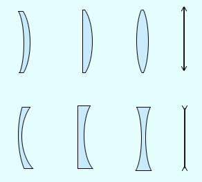
Types of lenses:
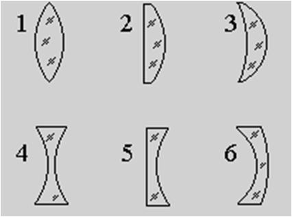
- convex:
- biconvex (1)
- plano-convex (2)
- concave-convex (3)
- concave:
- biconcave (4)
- flat-concave (5)
- convex-concave (6)
Basic designations in the lens:
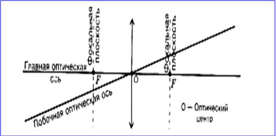
A straight line passing through the centers of curvature O 1 and O 2 of spherical surfaces is called main optical axis of the lens.
In the case of thin lenses, we can approximately assume that the main optical axis intersects with the lens at one point, which is usually called optical center of the lens O. The light beam passes through the optical center of the lens without deviating from its original direction.
Optical center of the lens- the point through which light rays pass without being refracted in the lens.
Main optical axis– a straight line passing through the optical center of the lens, perpendicular to the lens.
All straight lines passing through the optical center are called secondary optical axes.
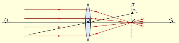
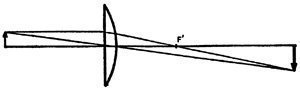
If a beam of rays parallel to the main optical axis is directed at a lens, then after passing through the lens the rays (or their continuation) will converge at one point F, which is called the main focus of the lens. A thin lens has two main foci, located symmetrically on the main optical axis relative to the lens. Converging lenses have real foci, while diverging lenses have imaginary foci.
Beams of rays parallel to one of the secondary optical axes, after passing through the lens, are also focused at point F", which is located at the intersection of the secondary axis with the focal plane Ф, that is, the plane perpendicular to the main optical axis and passing through the main focus.
Focal plane– a straight line, perpendicular to the main optical axis of the lens and passing through the focus of the lens.
The distance between the optical center of the lens O and the main focus F is called focal length . It is denoted by the same letter F.
Refraction of a parallel beam of rays in a collecting lens.
Refraction of a parallel beam of rays in a diverging lens.
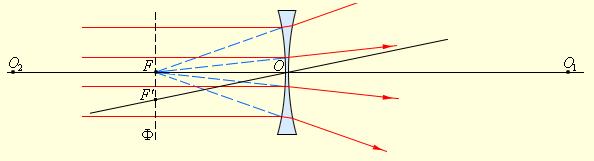
Points O 1 and O 2 are the centers of spherical surfaces, O 1 O 2 is the main optical axis, O is the optical center, F is the main focus, F" is the secondary focus, OF" is the secondary optical axis, Ф is the focal plane.
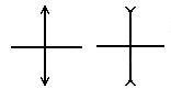
In the drawings, thin lenses are depicted as a segment with arrows:
collecting: 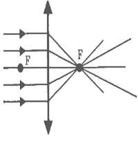 scattering:
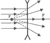
The main property of lenses– ability to give images of objects. Images come straight And upside down, valid And imaginary, enlarged And reduced.
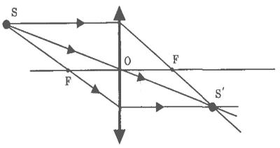
The position of the image and its character can be determined using geometric constructions. To do this, use the properties of some standard rays, the course of which is known. These are rays passing through the optical center or one of the focal points of the lens, as well as rays parallel to the main or one of the secondary optical axes. To construct an image in a lens, any two of three rays are used:
A ray incident on a lens parallel to the optical axis passes through the focus of the lens after refraction.
The ray passing through the optical center of the lens is not refracted.
The ray, passing through the focus of the lens after refraction, goes parallel to the optical axis.
The position of the image and its nature (real or imaginary) can also be calculated using the thin lens formula. If the distance from the object to the lens is denoted by d, and the distance from the lens to the image by f, then the formula for a thin lens can be written as:
![]()
The value D, the reciprocal of the focal length is called optical power of the lens.
The unit of measurement for optical power is diopter (dopter). Diopter – optical power of a lens with a focal length of 1 m: 1 diopter = m –1
It is customary to assign certain signs to the focal lengths of lenses: for a converging lens F > 0, for a diverging lens F< 0 .
The quantities d and f also obey a certain sign rule:
d > 0 and f > 0 – for real objects (that is, real light sources, and not extensions of rays converging behind the lens) and images;
d< 0 и f < 0 – для мнимых источников и изображений.
Thin lenses have a number of disadvantages that do not allow obtaining high-quality images. Distortions that occur during image formation are called aberrations. The main ones are spherical and chromatic aberration.
Spherical aberration manifests itself in the fact that in the case of wide light beams, rays far from the optical axis cross it out of focus. The thin lens formula is valid only for rays close to the optical axis. The image of a distant point source, created by a wide beam of rays refracted by a lens, turns out to be blurred.
Chromatic aberration occurs due to the fact that the refractive index of the lens material depends on the wavelength of light λ. This property of transparent media is called dispersion. The focal length of the lens turns out to be different for light with different lengths waves, which leads to blurring of the image when using non-monochromatic light.
Modern optical devices do not use thin lenses, but complex multi-lens systems in which various aberrations can be approximately eliminated.
The formation of a real image of an object by a converging lens is used in many optical instruments, such as a camera, projector, etc.
If you want to create a high-quality optical device, you should optimize a set of its main characteristics - aperture ratio, resolution and magnification. You cannot make a good telescope, for example, by achieving only high apparent magnification and leaving the aperture ratio (aperture) small. It will have poor resolution since it directly depends on the aperture. The designs of optical devices are very diverse, and their features are dictated by the purpose of specific devices. But when implementing any designed optical system into a finished optical-mechanical device, it is necessary to arrange all optical elements in strict accordance with the adopted scheme, securely fasten them, ensure precise adjustment of the position of moving parts, and place diaphragms to eliminate unwanted background scattered radiation. It is often necessary to maintain specified temperature and humidity values inside the device, minimize vibrations, normalize weight distribution, and ensure heat removal from lamps and other auxiliary electrical equipment. Value is given appearance device and ease of handling.
Microscope, magnifying glass, magnifying glass.
If we examine an object located behind the lens no further than its focal point through a positive (converging) lens, we see an enlarged virtual image subject. Such a lens is a simple microscope and is called a magnifying glass or magnifying glass.
The size of the enlarged image can be determined from the optical design.
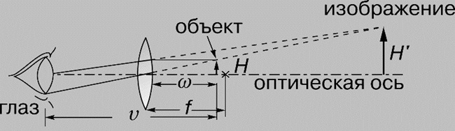
When the eye is tuned to a parallel beam of light (the image of the object is at an indefinitely large distance, which means that the object is located in the focal plane of the lens), the apparent magnification M can be determined from the relation: M = tgb /tga = (H/f)/( H/v) = v/f, where f is the focal length of the lens, v is the distance of best vision, i.e. the shortest distance at which the eye sees well with normal accommodation. M increases by one when the eye is adjusted so that the virtual image of the object is at the distance of best vision. Accommodation abilities are different for all people, and they worsen with age; 25 cm is considered to be the distance of best vision in a normal eye. In the field of view of a single positive lens, as one moves away from its axis, image sharpness quickly deteriorates due to transverse aberrations. Although there are loupes with a magnification of 20x, their typical magnification is from 5 to 10. The magnification of a compound microscope, usually called simply a microscope, reaches up to 2000x.
Telescope.
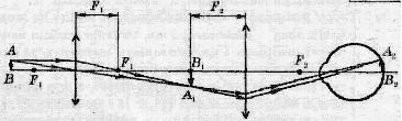
A telescope increases the apparent size of distant objects. The simplest telescope circuit includes two positive lenses.
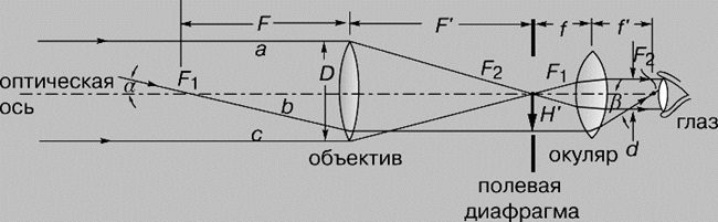
Rays from a distant object, parallel to the axis of the telescope (rays a and c in the diagram), are collected at the rear focus of the first lens (objective). The second lens (eyepiece) is removed from the focal plane of the lens at its focal length, and rays a and c emerge from it again parallel to the axis of the system. Some ray b, emanating from points other than those on the object from which rays a and c came, falls at an angle a to the axis of the telescope, passes through the front focus of the lens and after it goes parallel to the axis of the system. The eyepiece directs it to its back focus at an angle b. Since the distance from the front focus of the lens to the observer's eye is negligible compared to the distance to the object, from the diagram we can obtain an expression for the apparent magnification M of the telescope: M = -tgb /tga = -F/f" (or F/f). Negative the sign indicates that the image is inverted. In astronomical telescopes it remains so; in telescopes for observing terrestrial objects, an inverting system is used to view normal, rather than inverted, images. The inverting system may include additional lenses or, as in binoculars, prisms.
Binoculars.
A binocular telescope, commonly referred to as binoculars, is a compact instrument for observing with both eyes at the same time; its increase is usually from 6 to 10 times. Binoculars use a pair of wraparound systems (most often Porro), each of which includes two rectangular prisms (with a base at 45°), oriented towards each other with rectangular edges.
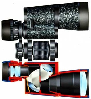
To obtain high magnification over a wide field of view, free from lens aberrations, and therefore a significant viewing angle (6-9°), binoculars need a very high-quality eyepiece, more advanced than a telescope with a narrow angle of view. The eyepiece of the binoculars provides for image focusing, and with vision correction - its scale is marked in diopters. In addition, in binoculars the position of the eyepiece is adjusted to the distance between the observer's eyes. Typically, binoculars are labeled according to their magnification (in multiples) and lens diameter (in millimeters), for example, 8*40 or 7*50.
Optical sight.
Any telescope for ground-based observations can be used as an optical sight if clear marks (grids, marks) corresponding to a given purpose are applied in any plane of its image space. The typical design of many military optical installations is such that the telescope lens is openly looking at the target, and the eyepiece is in a shelter. This scheme requires a bend in the optical axis of the sight and the use of prisms to shift it; these same prisms convert the inverted image into a direct one. Systems with a displacement of the optical axis are called periscopic. Typically, an optical sight is designed so that the pupil of its exit is located at a sufficient distance from the last surface of the eyepiece to protect the gunner's eye from hitting the edge of the telescope during recoil of the weapon.
Rangefinder.
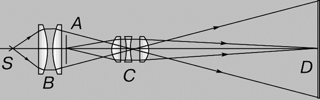
Optical rangefinders, which measure distances to objects, come in two types: monocular and stereoscopic. Although they differ in design details, the main part of the optical design is the same and the principle of operation is the same: using the known side (base) and two known angles of the triangle, its unknown side is determined. Two parallel oriented telescopes, separated by a distance b (base), construct images of the same distant object so that it appears to be observed from them in different directions(the size of the target can also serve as a basis). If, using some suitable optical device, the image fields of both telescopes are combined so that they can be viewed simultaneously, it turns out that the corresponding images of the object are spatially separated. There are rangefinders not only with full field overlap, but also with half field overlap: the upper half of the image space of one telescope is combined with the lower half of the image space of the other. In such devices, using a suitable optical element, spatially separated images are combined and the measured value is determined from the relative shift of the images. Often the shearing element is a prism or a combination of prisms.
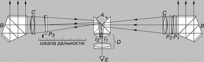
MONOCULAR RANGE FINDER. A- rectangular prism; B - pentaprisms; C - lens objectives; D - eyepiece; E - eye; P1 and P2 are fixed prisms; P3 - movable prism; I 1 and I 2 - images of halves of the field of view
In the monocular rangefinder circuit shown in the figure, this function is performed by prism P3; it is associated with a scale graduated in measured distances to the object. Pentaprisms B are used as light reflectors at right angles, since such prisms always deflect the incident light beam by 90°, regardless of the accuracy of their installation in the horizontal plane of the device. In a stereoscopic rangefinder, the observer sees the images created by two telescopes with both eyes at once. The base of such a rangefinder allows the observer to perceive the position of an object three-dimensionally, at a certain depth in space. Each telescope has a reticle with marks corresponding to the range values. The observer sees a distance scale going deep into the depicted space, and uses it to determine the distance of the object.
Lighting and projection devices. Spotlights.
In the optical design of the spotlight, the light source, for example the crater of an electric arc discharge, is located at the focus of a parabolic reflector. Rays emanating from all points of the arc are reflected by a parabolic mirror almost parallel to each other. The beam of rays diverges slightly because the source is not luminous point, and the volume is of finite size.
Diascope.
The optical design of this device, designed for viewing transparencies and transparent color frames, includes two lens systems: a condenser and a projection lens. The condenser evenly illuminates the transparent original, directing the rays into the projection lens, which builds an image of the original on the screen. The projection lens provides focusing and replacement of its lenses, which allows you to change the distance to the screen and the size of the image on it. The optical design of the film projector is the same.
DIASCOPE DIAGRAM. A - slide; B - lens condenser; C - projection objective lenses; D - screen; S - light source
Spectral devices.
The main element of a spectral device can be a dispersion prism or a diffraction grating. In such a device, the light is first collimated, i.e. is formed into a beam of parallel rays, then decomposed into a spectrum, and finally, the image of the input slit of the device is focused onto its output slit at each wavelength of the spectrum.
Spectrometer.
In this more or less universal laboratory device, the collimating and focusing systems can be rotated relative to the center of the stage on which the element is located that decomposes light into a spectrum. The device has scales for reading the angles of rotation, for example, a dispersion prism, and the angles of deflection after it of different color components of the spectrum. Based on the results of such readings, for example, the refractive indices of transparent solids are measured.
Spectrograph.
This is the name of a device in which the resulting spectrum or part of it is recorded on photographic material. You can obtain a spectrum from a prism made of quartz (range 210-800 nm), glass (360-2500 nm) or rock salt(2500-16000 nm). In those spectral ranges where the prisms weakly absorb light, the images of spectral lines in the spectrograph are bright. In spectrographs with diffraction gratings, the latter perform two functions: they decompose the radiation into a spectrum and focus the color components onto the photographic material; Such devices are also used in the ultraviolet region.
Camera It is a closed, light-tight chamber. The image of the objects being photographed is created on photographic film by a system of lenses called a lens. A special shutter allows you to open the lens for the duration of the exposure.
A special feature of the camera is that flat film should produce fairly sharp images of objects located at different distances.
In the film plane, only images of objects located at a certain distance are sharp. Focusing is achieved by moving the lens relative to the film. Images of points that do not lie in the sharp pointing plane appear blurred in the form of scattering circles. The size d of these circles can be reduced by stopping down the lens, i.e. decreasing the relative opening a/F. This results in an increase in depth of field.
The lens of a modern camera consists of several lenses combined into optical systems(for example, Tessar optical design). The number of lenses in the lenses of the simplest cameras is from one to three, and in modern expensive cameras there are up to ten or even eighteen.
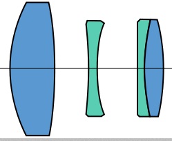
Optical design of Tessar
There can be from two to five optical systems in the lens. Almost all optical circuits are designed and work the same way - they focus light rays passing through the lenses onto a photosensitive matrix.
The quality of the image in the photo depends only on the lens, whether the photo will be sharp, whether the shapes and lines in the photo will be distorted, whether it will convey colors well - all this depends on the properties of the lens, which is why the lens is one of the most important elements of a modern camera.
Objective lenses are made from special types of optical glass or optical plastic. Creating lenses is one of the most expensive parts of creating a camera. When comparing glass and plastic lenses, it is worth noting that plastic lenses are cheaper and lighter. Currently, most lenses on inexpensive amateur compact cameras are made of plastic. But such lenses are susceptible to scratches and are not so durable; after about two to three years they become cloudy, and the quality of photographs leaves much to be desired. The optics of more expensive cameras are made of optical glass.
Nowadays, most compact camera lenses are made of plastic.
The objective lenses are glued or connected to each other using very precisely calculated metal frames. Gluing lenses can be found much more often than metal frames.
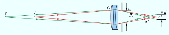
Projection apparatus designed for obtaining large-scale images. The projector lens O focuses the image of a flat object (slide D) on a distant screen E. A lens system K, called a condenser, is designed to concentrate the light of the source S on the slide. On screen E a real enlarged inverted image is created. The magnification of the projection apparatus can be changed by moving the screen E closer or further away while simultaneously changing the distance between the slide D and the lens O.
Full text search:
Home > Abstract >Physics
Types of lenses
Reflection Andrefraction Lights are used to change the direction of rays or, as they say, to control light beams. This is the basis for the creation of specialoptical instruments , such as a magnifying glass, telescope, microscope, camera and others. The main part of most of them islens . For example,glasses - These are lenses enclosed in a frame. This example alone shows how important the use of lenses is for a person.
For example, in the first picture the flask is as we see it in life,
and on the second, if we look at it through a magnifying glass (the same lens).
Most often used in optics spherical lenses. Such lenses are bodies made of optical or organic glass, limited by two spherical surfaces.
Lenses are transparent bodies bounded on both sides by curved surfaces (convex or concave). StraightAB,passing through the centers C1 and C2 of the spherical surfaces limiting the lens is called the optical axis.
This figure shows cross sections of two lenses with centers at point O. The first lens shown in the figure is called convexly, second - concave. Point O, lying on the optical axis at the center of these lenses, is called optical center of the lens.
One of the two bounding surfaces may be flat.
WITH 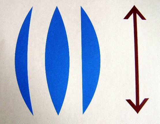 left lenses are convex,
on the right - concave.
We will consider only spherical lenses, that is, lenses bounded by two spherical surfaces.
Lenses bounded by two convex surfaces are called biconvex; lenses bounded by two concave surfaces are called biconcave.
By directing a beam of rays parallel to the main optical axis of the lens at a convex lens, we will see that after refraction in the lens, these rays are collected at a point called main focus lenses 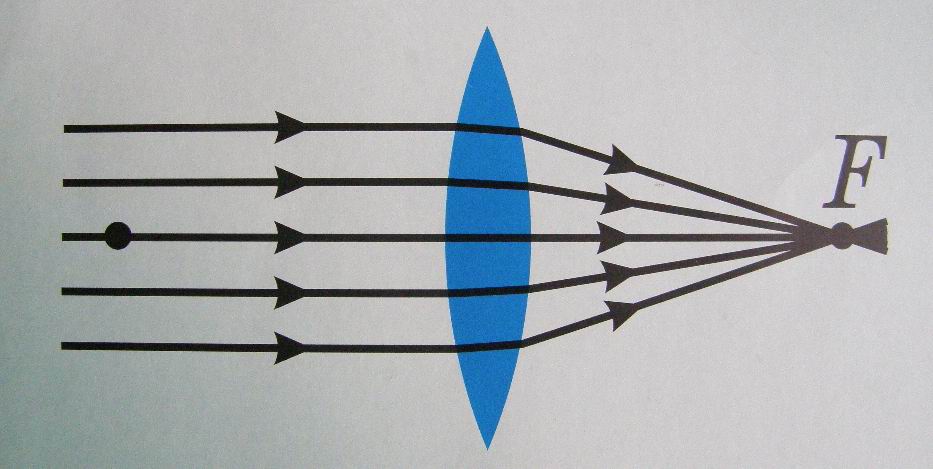 - point F. The lens has two main foci, on both sides at the same distance from the optical center. If the light source is in focus, then after refraction in the lens the rays will be parallel to the main optical axis. Every lens has two focal points - one on each side of the lens. The distance from a lens to its focus is called the focal length of the lens.
Let us direct a beam of diverging rays from a point source lying on the optical axis to a convex lens. If the distance from the source to the lens is greater than the focal distance, then the rays after refraction in the lens will cross optical axis lenses at one point. Consequently, a convex lens collects rays coming from sources located from the lens at a distance greater than its focal length. Therefore, a convex lens is otherwise called a converging lens.
When rays pass through a concave lens, a different picture is observed.
Let us send a beam of rays parallel to the optical axis onto a biconcave lens. We will notice that the rays will emerge from the lens in a diverging beam. If this diverging beam of rays hits the eye, then it will seem to the observer that the rays are coming out from a pointF.This point is called the imaginary focus of a biconcave lens. Such a lens can be called diverging.
Figure 63 explains the action of converging and diverging lenses. Lenses can be represented as a large number of prisms. Since prisms deflect rays, as shown in the figures, it is clear that lenses with thickening in the middle collect the rays, and lenses with thickening at the edges scatter them. The middle of the lens acts like a plane-parallel plate: it does not deflect rays in either the collecting or diverging lens
In the drawings, converging lenses are designated as shown in the figure on the left, and diverging lenses - in the figure on the right.
Among convex lenses distinguished: biconvex, plano-convex and concave-convex (respectively in the figure). All convex lenses have a wider middle cut than the edges. These lenses are called collecting.
WITH 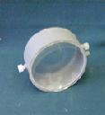 Among concave lenses there are biconcave, plano-concave and convex-concave (respectively in the figure). All concave lenses have a narrower middle section than the edges. These lenses are called scattering.
Light is electromagnetic radiation perceived by the eye through visual sensation.
Law of rectilinear propagation of light: light propagates rectilinearly in a homogeneous medium
A light source whose dimensions are small compared to the distance to the screen is called a point light source.
The incident beam and the reflected beam lie in the same plane with the perpendicular restored to the reflecting surface at the point of incidence. The angle of incidence is equal to the angle of reflection.
If a point object and its reflection are swapped, the path of the rays will not change, only their direction will change.
A yawning reflective surface is called flat mirror, if a beam of parallel rays incident on it remains parallel after reflection.
A lens whose thickness is much less than the radii of curvature of its surfaces is called a thin lens.
A lens that converts a beam of parallel rays into a converging one and collects it into one point is called a converging lens.
A lens that converts a beam of parallel rays into a diverging one - diverging.
For a collecting lens
For a diverging lens:
For all positions of the object, the lens gives a reduced, imaginary, direct image, lying on the same side of the lens as the object.
Properties of the eye:
accommodation (achieved by changing the shape of the lenses);
adaptation (adaptation to different lighting conditions);
visual acuity (the ability to separately distinguish two close points);
field of view (the space observed when the eyes move but the head remains stationary)
Visual impairments
myopia (correction - diverging lens);
farsightedness (correction - converging lens).
A thin lens represents the simplest optical system. Simple thin lenses are used mainly in the form of glasses for glasses. In addition, the use of a lens as a magnifying glass is well known.
The action of many optical instruments - a projection lamp, a camera and other devices - can be schematically compared to the action of thin lenses. However, a thin lens gives good picture only in the relatively rare case when one can limit oneself to a narrow single-color beam coming from the source along the main optical axis or under high angle To her. In most practical problems, where these conditions are not met, the image produced by a thin lens is rather imperfect.
Therefore, in most cases, they resort to constructing more complex optical systems that have a large number of refractive surfaces and are not limited by the requirement of proximity of these surfaces (a requirement that is satisfied by a thin lens). [ 4 ]
4.2 Photographic apparatus. Opticaldevices.
All optical instruments can be divided into two groups:
1) devices with which optical images are obtained on a screen. These includeprojection devices , cameras , movie cameras, etc.
2) devices that operate only in conjunction with human eyes and do not form images on the screen. These includemagnifying glass , microscope and various system devicestelescopes . Such devices are called visual.
Camera.
WITH 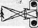 Modern cameras have a complex and varied structure, but we will look at what basic elements a camera consists of and how they work.
The main part of any camera is lens - a lens or lens system placed in the front of a light-proof camera body (Fig. left). The lens can be smoothly moved relative to the film to obtain a clear image of objects close or distant from the camera.
When photographing, the lens is opened slightly using a special shutter, which allows light to enter the film only at the moment of photographing. Diaphragm regulates the light flux that hits the film. The camera produces a reduced, inverse, real image, which is recorded on film. Under the influence of light, the composition of the film changes and the image is imprinted on it. It remains invisible until the film is dipped into a special solution - a developer. Under the influence of the developer, those parts of the film on which the light fell darken. The more light an area of the film has been exposed to, the darker it will be after development. The resulting image is called negative(from Latin negativus - negative), on it the light parts of the object appear dark, and the dark parts appear light.


To prevent this image from changing under the influence of light, the developed film is immersed in another solution - a fixative. The photosensitive layer of those areas of the film that were not affected by light dissolves in it and is washed away. The film is then washed and dried.
They get from the negative positive(from Latin pozitivus - positive), i.e. an image in which dark places are located in the same way as on the photographed object. To do this, the negative is applied to paper also coated with a photosensitive layer (to photographic paper), and illuminated. Then the photographic paper is dipped into the developer, then into the fixer, washed and dried.
After developing the film, when printing photographs, a photo enlarger is used, which enlarges the image of the negative on photographic paper.
Magnifier.
To better see small objects, you have to use magnifying glass
A magnifying glass is a biconvex lens with a small focal length (from 10 to 1 cm). A magnifying glass is the simplest device that allows you to increase the angle of view.
N  Your eye sees only those objects whose images are captured on the retina. The larger the image of an object, the greater the angle of view from which we view it, the more clearly we distinguish it. Many objects are small and visible from the distance of best vision at a viewing angle close to the maximum. The magnifying glass increases the angle of view, as well as the image of the object on the retina of the eye, so the apparent dimensions of the object
 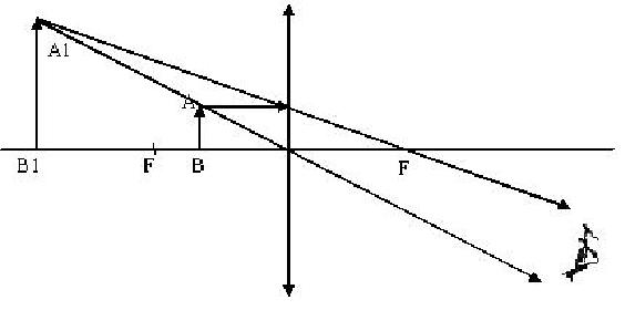 increase compared to its actual size.
ItemABplaced at a distance slightly less than the focal length from the magnifying glass (Fig. on the right). In this case, the magnifying glass gives a direct, enlarged, mental imageA1 B1.The magnifying glass is usually placed so that the image of the object is at the best viewing distance from the eye.
Microscope.
To obtain large angular magnifications (from 20 to 2000) and 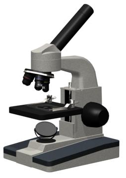 optical microscopes are used. An enlarged image of small objects in a microscope is obtained using an optical system, which consists of a lens and an eyepiece.
The simplest microscope is a system with two lenses: an objective and an eyepiece. ItemABplaced in front of the lens, which is the objective, at a distanceF 1< d < 2F 1 and is viewed through an eyepiece, which is used as a magnifying glass. The magnification G of the microscope is equal to the product of the magnification of the objective lens G1 and the magnification of the eyepiece G2:
The principle of operation of a microscope comes down to a sequential increase in the angle of view, first with the lens, and then with the eyepiece.
Projection apparatus.
P  projection devices are used to obtain enlarged images. Overhead projectors are used to obtain still images, and with the help of film projectors they obtain frames that quickly replace each other.
 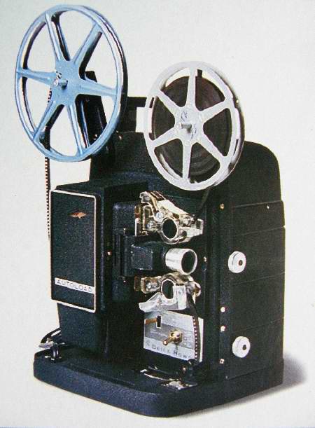 words and are perceived by the human eye as moving images. In a projection apparatus, a photograph on a transparent film is placed from the lens at a distanced,which satisfies the condition:F<
d < 2F
. To illuminate the film, an electric lamp 1 is used. To concentrate the light flux, a condenser 2 is used, which consists of a system of lenses that collect diverging rays from the light source on the film frame 3. Using the lens 4, an enlarged, direct, real image is obtained on the screen 5
words and are perceived by the human eye as moving images. In a projection apparatus, a photograph on a transparent film is placed from the lens at a distanced,which satisfies the condition:F<
d < 2F
. To illuminate the film, an electric lamp 1 is used. To concentrate the light flux, a condenser 2 is used, which consists of a system of lenses that collect diverging rays from the light source on the film frame 3. Using the lens 4, an enlarged, direct, real image is obtained on the screen 5
Telescope.
D 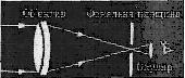 Spotting scopes or telescopes are used to view distant objects. The purpose of a telescope is to collect as much light as possible from the object under study and increase its apparent angular dimensions.
The main optical part of the telescope is the lens, which collects light and creates an image of the source.
E 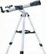 There are two main types of telescopes: refractors (lens-based) and reflectors (mirror-based).
The simplest telescope - a refractor, like a microscope, has a lens and an eyepiece, but unlike a microscope, the telescope lens has a long focal length, and the eyepiece has a short one. Since cosmic bodies are at very large distances from us, the rays from them come in a parallel beam and are collected by the lens in the focal plane, where a reverse, reduced, real image is obtained. To make the image straight, use another lens. form
Axes of rotation lenses. After processing diameter lenses controlled with a bracket. Faceting lenses. Faceting lenses- this... is finally cut off. All kinds structural chamfers are applied after centering lenses. Faceting is performed...
Highest value for optometry has the passage of light through the lenses. A lens is a body made of a transparent material, bounded by two refractive surfaces, at least one of which is a surface of rotation.
Let's consider the simplest lens - a thin one, limited by one spherical and one flat surface. Such a lens is called spherical. It is a segment sawn off from a glass ball. The line AO connecting the center of the ball to the center of the lens is called its optical axis. In cross-section, such a lens can be imagined as a pyramid made up of small prisms with an increasing angle at the apex.
Rays entering the lens and parallel to its axis undergo refraction, the greater the further they are from the axis. It can be shown that they will all intersect the optical axis at one point (F"). This point is called the focus of the lens (more precisely, the back focus). A lens with a concave refractive surface has the same point, but its focus is on the same side from where rays come in. The distance from the focal point to the center of the lens is called its focal length (f"). The reciprocal of the focal length characterizes the refractive power, or refraction, of the lens (D):
Where D is the refractive power of the lens, diopters; f—focal length, m;
The refractive power of a lens is measured in diopters. It is the basic unit in optometry. The refractive power of a lens with a focal length of 1 m is taken as 1 diopter (D, diopter). Therefore, a lens with a focal length of 0.5 m has a refractive power of 2.0 diopter, 2 m - 0.5 diopter, etc. Refractive power convex lenses have a positive value, concave lenses have a negative value.
Not only rays parallel to the optical axis, passing through a convex spherical lens, converge at one point. Rays emanating from any point to the left of the lens (not closer than the focal point) converge to another point to the right of it. Thanks to this, a spherical lens has the ability to form images of objects.
Just like plano-convex and plano-concave lenses, lenses limited by two spherical surfaces operate - biconvex, biconcave and convex-concave. In spectacle optics they are mainly used convex-concave lenses, or menisci. The overall effect of the lens depends on which surface has the greater curvature.
The action of spherical lenses is called stigmatic (from the Greek - point), since they form an image of a point in space in the form of a point.
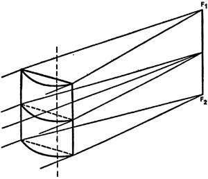
The following types of lenses are cylindrical and toric. A convex cylindrical lens has the property of collecting a beam of parallel rays incident on it into a line parallel to the axis of the cylinder. Straight line F1F2, by analogy with the focal point of a spherical lens, is called the focal line.
A cylindrical surface, when intersected by planes passing through the optical axis, forms a circle, ellipses and a straight line in sections. Two such sections are called main: one passes through the axis of the cylinder, the other is perpendicular to it. In the first section a straight line is formed, in the second - a circle. Accordingly, in a cylindrical lens there are two main sections, or meridians, - the axis and the active section. Normal rays incident on the axis of the lens are not subject to refraction, but incident on the active section are collected at the focal line, at the point of its intersection with the optical axis.
More complex is a lens with a toric surface, which is formed by rotating a circle or arc of radius r around an axis. The radius of rotation R is not equal to the radius r.
Yu.Z. Rosenblum


 Elder Macarius of Egypt")


- Temple of the Tikhvin Icon of the Mother of God on Ave.
- Step-by-step recipe for making pies with potatoes in the oven
- Oven pies with potatoes
- Recipes for simple and tasty salads with croutons
- Recipes for simple and tasty salads with croutons
- Fish soup Sea bass recipes for cooking fish soup
- Chicken hearts in sour cream
- Chicken hearts in sour cream: recipes
- Recipe for lavash envelopes with cheese
- Preparation of canned fish from mackerel
- Mackerel in oil in a slow cooker: a recipe for preparing delicious canned food for the winter
- Castling Shah Galina Dolova read in full
- Book Review: Tony Buzan's "Speed Reading Workbook Training Angle of View for Speed Reading"
- Reverend David of Serpukhov
- Venerable Macarius the Great, Egyptian (†391) Elder Macarius of Egypt
- What does the “Desperate One Hope” icon help with?
- Church of the Assumption of the Blessed Virgin Mary
- Boris Khramtsov. Eyes looking to the sky. "he knew something that I had long forgotten"
- The tomb of Blessed Alexandra and the August icon in the darna
- Temple of the Placing of the Robe on Donskoy