How does the image appear in the lens? Virtual image
Let us assume that a luminous point lying on the main axis of the lens moves away from the lens to a very large distance. In this case, the rays incident on the lens will tend to become parallel to its main axis. We saw in § 88 that after refraction in the lens, these rays will converge at the focus of the lens. In formula (89.6), when the source moves away to a very large distance, the value tends to zero, and we get
that is, we can say that the focus is the image of the “infinitely distant” point.
An example of an almost infinitely distant source can be any celestial body. Consequently, the images of stars, the Sun, etc. will be at the focus of the lens. Terrestrial light sources that are sufficiently far from the lens also produce an image at its focus.
Let us now assume that the image of a certain point is removed at a very large distance, that is, a beam of light rays parallel to the main axis emerges from the lens. In this case, as we saw in § 88, the source must be at the front focus of the lens (Fig. 196). This conclusion also follows from formula (89.6). Indeed, assuming that the image is at infinity, we obtain ; in this case, the distance of the source from the lens is equal to the focal length: .
Different lenses differ from each other in the location of the centers of the spherical surfaces that form them, their radii and the refractive indices of the substance from which the lenses are made. In Fig. 198 presents six main types of lenses.
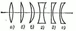
Rice. 198. Different types of lenses. If the lens material refracts more strongly than the environment, then types a, b, c are collecting; types d, e, f – scattering.
If parallel rays, after refraction in the lens, converge, actually intersecting at some point lying on the other side of the lens, then the lens is called collecting or positive (Fig. 199, a). If parallel rays, after refraction in the lens, become divergent (Fig. 199, b), then the lens is called divergent or negative. In the case of a diverging lens, it is not the refracted rays that intersect at the focus, but their imaginary extensions; in this case, the focus lies on the same side of the lens from which a parallel beam of rays falls on the lens. The focuses in this case are called imaginary (Fig. 199, 6).
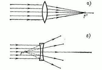
Rice. 199. The actual focus of a collecting lens (a) and imaginary focus diverging lens (b)
Typically, the lens material refracts more than the surrounding medium (eg a glass lens in air). Then the converging lenses are lenses that thicken from the edges to the middle - biconvex and plano-convex lenses and a positive meniscus (concave-convex lens; Fig. 198, a-c). Diffusing lenses are lenses that become thinner towards the middle: biconcave, plano-concave lenses and a negative meniscus (convex-concave lens; 198, d - e). If the lens material refracts weaker than the surrounding medium, i.e. relative refractive index, then, on the contrary, lenses a, b, c (Fig. 198) will be divergent, and lenses d, e, f will be converging. Such lenses can be obtained, for example, by forming an air cavity of the appropriate shape in water with two watch glasses glued together with wax (Fig. 200).
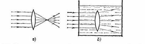
Rice. 200. Biconvex lenses: a) glass in the air - converging; b) air in water - scattering
Let's move on to considering luminous points located at a finite distance from the lens. We will always consider the sources to be located to the left of the lens. As for images, depending on the type of lens and the position of the source relative to it, the image can be located either to the right or to the left of the lens. If the image lies to the right of the lens, then this means that it is formed by a converging beam of rays (Fig. 201, a), that is, rays that actually pass through the point. The image in this case is called real. It can be obtained on a screen, photographic plate, etc. By reconstructing the path of the rays that led to the formation of the image, we can always find the location of the source, although in practice this is usually associated with some difficulties.
Let us now assume that the image lies to the left of the lens, that is, on the same side of it as the source. This means that a beam of rays diverging from the source, after refraction in the lens, becomes even more divergent, and only imaginary continuations of the refracted rays intersect at the point (Fig. 201, b). The image in this case is called imaginary.
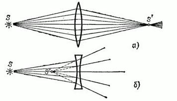
Rice. 201. The source and the actual image lie on different sides of the lens (a); the virtual image is located on the same side of the lens as the source (b)
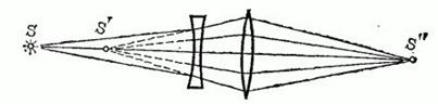
The term “virtual image”, rooted in optics, can lead to some misunderstandings. In reality, of course, there is nothing “imaginary” in this case. The peculiarity of imaginary images is that they cannot be obtained directly on a screen, photographic plate, etc. For example, if you place a very small screen at a point (Fig. 201, b) , which does not interfere with the majority of the rays hitting the lens, then we will not get on it luminous point. However, a diverging beam of rays, the imaginary extensions of which intersect in an imaginary image, in itself has nothing “imaginary”. This beam can be converted into a convergent beam if a properly selected collecting lens is placed in its path. Then on the screen or photographic plate we will have a real image of a luminous point (Fig. 202), which at the same time can be considered as an image of an “imaginary point”.
The role of such a converging lens is also performed by the human eye; On the photosensitive shell of the eye - the retina - rays diverging from light sources are collected. A beam of diverging rays, whether they come from a real point source or from its virtual image, can be collected by the optical system of the eye into a single point on the retina. IN Everyday life the observer acquires the habit of automatically reconstructing the course of the rays that produced the image on the retina and determining the location of the source. When a diverging beam of rays (with apex at ), shown in Fig., enters the eye. 202, then, “restoring” the place where these rays came from, we are in and d and m at the source point, although in reality there is no source at this point. It is this imaginary source that we call the “imaginary” image of a point.
Rice. 202. Transformation of a diverging beam of rays into a converging one using an auxiliary collecting lens (for example, an eye)
Using formula (89.6), it is easy to see how the position of the image changes as the source moves along the main optical axis (see exercises 31, 32 at the end of this chapter).
Optical image- a picture obtained as a result of the passage of light rays propagating from an object through an optical system, and reproducing its contours and details.
In practice, they often change the scale of the image of objects and project it onto some surface.
Correspondence to an object is achieved when each of its points is represented by a point, at least approximately. In this case, two cases are distinguished: a real image and a virtual image.
- Real Image is created when, after all reflections and refractions, the rays emerging from one point of an object are collected at one point.
The actual image cannot be seen directly, but a projection of it can be seen simply by placing a diffusion screen. The real is created by such optical systems as a lens (for example, a film projector or camera) or one positive lens.
- Virtual image- something that can be seen with the eye. In this case, each point of the object corresponds to one emerging from optical system a bundle of rays, which, if extended back in straight lines, would converge at one point; it appears that the beam comes out from there. A virtual image is created by optical systems such as binoculars, microscopes, negative or positive lenses (magnifying glasses), and also a flat mirror.
In any real optical system, aberrations are inevitably present, as a result of which the rays (or their extensions) do not converge perfectly at one point, and in addition, they do not converge as closely as possible exactly where they should. The image turns out somewhat blurry and geometrically not completely similar to the object; Other defects are possible.
A beam of rays that diverges from or converges at one point is called homocentric. It corresponds to a spherical light wave. The task of most optical systems is to transform diverging homocentric beams into homocentric ones, thereby creating an imaginary or real image, most often on a different scale in relation to the object.
Stigmatic image (from ancient Greek. στίγμα - prick, scar) - an optical image, each point of which corresponds to one point of the object depicted by the optical system.
A stigmatic image is not necessarily geometrically similar to the depicted object, but if it is similar, such an image is called ideal. This is possible only under the condition that all aberrations are absent or eliminated in the optical system, and that it is possible to neglect the wave properties of light. An optical system that produces a perfect image is called an ideal optical system. Centered systems, in which the image is obtained using monochromatic and paraxial light beams, can be approximately considered ideal.
Notes
Literature
- Physical Encyclopedia, Vol. II. M., “Soviet Encyclopedia”, 1990. (Article “Optical image.”)
- Yavorsky B. M., Detlaf A. A. Handbook of Physics. - M.: “Science”, Ed. company "Phys.-math. lit.”, 1996.
- Sivukhin D.V. General course physics. Optics. M., “Science”, 1985.
- Volosov D.S. Photographic optics. M., “Iskusstvo”, 1971.
see also
Wikimedia Foundation. 2010.
See what a “Virtual Image” is in other dictionaries:
- (see OPTICAL IMAGE). Physical encyclopedic Dictionary. M.: Soviet Encyclopedia. Chief Editor A. M. Prokhorov. 1983. VIMARY IMAGE... Physical encyclopedia
Big Encyclopedic Dictionary
VIMARY IMAGE- cm … Big Polytechnic Encyclopedia
See optical image. * * * VIMARY IMAGE VIMARY IMAGE, see Optical image (see OPTICAL IMAGE) ... encyclopedic Dictionary
virtual image- menamasis vaizdas statusas T sritis fizika atitikmenys: engl. apparent image; virtual image vok. scheinbares Bild, n; virtuelles Bild, n rus. virtual image, n pranc. image virtuelle, f … Fizikos terminų žodynas
An object (perceived by the eye as an object) is formed by the intersections of geometric extensions of light rays passing through the optical system in directions opposite to the actual path of these rays. See image for details... ... Great Soviet Encyclopedia
See image optical...
OPTICAL IMAGE, image of an object using an optical device. The actual image is formed by a set of points at which rays of light passing through an optical device converge. Through the points forming a virtual image... ... Scientific and technical encyclopedic dictionary
The image of an object obtained as a result of the action of optical systems on light rays emitted or reflected by an object. And about. reproduces the contours and details of an object with certain distortions (aberrations of optical systems). There are valid And… … Natural science. encyclopedic Dictionary
Optical image is a picture obtained as a result of light rays propagating from an object passing through an optical system and reproducing its contours and details. In practice, they often change the scale of images of objects and... ... Wikipedia
Real Image
Optical image- a picture obtained as a result of the passage of light rays propagating from an object through an optical system, and reproducing its contours and details.
In practice, they often change the scale of the image of objects and project it onto some surface.
Correspondence to an object is achieved when each of its points is represented by a point, at least approximately. In this case, two cases are distinguished: a real image and a virtual image.
- Real Image is created when, after all reflections and refractions, the rays emerging from one point of an object are collected at one point.
The actual image cannot be seen directly, but a projection of it can be seen simply by placing a diffusion screen. The real is created by such optical systems as a lens (for example, a film projector or camera) or one positive lens.
- Virtual image- something that can be seen with the eye. In this case, each point of the object corresponds to a beam of rays emerging from the optical system, which, if extended back in straight lines, would converge at one point; it appears that the beam comes out from there. A virtual image is created by optical systems such as binoculars, microscopes, negative or positive lenses (magnifying glasses), and also a flat mirror.
In any real optical system, aberrations are inevitably present, as a result of which the rays (or their extensions) do not converge perfectly at one point, and in addition, they do not converge as closely as possible exactly where they should. The image turns out somewhat blurry and geometrically not completely similar to the object; Other defects are possible.
A beam of rays that diverges from or converges at one point is called homocentric. It corresponds to a spherical light wave. The task of most optical systems is to transform diverging homocentric beams into homocentric ones, thereby creating an imaginary or real image, most often on a different scale in relation to the object.
Stigmatic image (from ancient Greek. στίγμα - prick, scar) - an optical image, each point of which corresponds to one point of the object depicted by the optical system.
A stigmatic image is not necessarily geometrically similar to the depicted object, but if it is similar, such an image is called ideal. This is possible only under the condition that all aberrations are absent or eliminated in the optical system, and that it is possible to neglect the wave properties of light. An optical system that produces a perfect image is called an ideal optical system. Centered systems, in which the image is obtained using monochromatic and paraxial light beams, can be approximately considered ideal.
Notes
Literature
- Physical Encyclopedia, Vol. II. M., “Soviet Encyclopedia”, 1990. (Article “Optical image.”)
- Yavorsky B. M., Detlaf A. A. Handbook of Physics. - M.: “Science”, Ed. company "Phys.-math. lit.”, 1996.
- Sivukhin D.V. General physics course. Optics. M., “Science”, 1985.
- Volosov D.S. Photographic optics. M., “Iskusstvo”, 1971.
see also
Wikimedia Foundation. 2010.
See what a “Real image” is in other dictionaries:
See Art. Optical image... Big Encyclopedic Dictionary
- (see OPTICAL IMAGE). Physical encyclopedic dictionary. M.: Soviet Encyclopedia. Editor-in-chief A. M. Prokhorov. 1983 ... Physical encyclopedia
See the article Optical image. * * * ACTUAL IMAGE ACTUAL IMAGE, see art. Optical image (see OPTICAL IMAGE) ... encyclopedic Dictionary
real image- realusis vaizdas statusas T sritis fizika atitikmenys: engl. real image; true image vok. reelles Bild, n; wirkliches Bild, n rus. real image, n; true image, n pranc. image réelle, f … Fizikos terminų žodynas
See image optical... Great Soviet Encyclopedia
See Art. Optical image...
A picture obtained as a result of the passage of rays propagating from an object through an optical system, reproducing its contours and details. In practical using I. o. take advantage of the ability to change the scale of images of objects... ... Physical encyclopedia
OPTICAL IMAGE, image of an object using an optical device. The actual image is formed by a set of points at which rays of light passing through an optical device converge. Through the points forming a virtual image... ... Scientific and technical encyclopedic dictionary
Optical image is a picture obtained as a result of light rays propagating from an object passing through an optical system and reproducing its contours and details. In practice, they often change the scale of images of objects and... ... Wikipedia
The image of an object obtained as a result of the action of optical systems on light rays emitted or reflected by an object. And about. reproduces the contours and details of an object with certain distortions (aberrations of optical systems). There are valid And… … Natural science. encyclopedic Dictionary
Geometric optics explains many simple optical phenomena, such as the occurrence of shadows and the formation of images in optical instruments. It makes it possible to relatively easily examine the passage of light through any optical system and gives
opportunity by simple means decide wide circle practically important tasks.
However, to solve more subtle issues, such as the distribution of light near the focus or the resolution of optical instruments, we need to go beyond geometric optics and taking into account the wave nature of light. As already noted in § 33, the image of a distant star in the focal plane of a telescope lens is not a point, but a diffraction spot.
Geometric optics and wave properties of light. According to the concepts of geometric optics, the image of a point on an object is the intersection of a beam of rays. However, near this intersection point, the curvature of the wave surface becomes so significant that it can no longer be considered flat at distances of the order of the wavelength. Near such points, the conditions for the applicability of geometric optics are obviously not met: the luminous flux cannot be collected at one point, because this would lead to an infinitely large illumination, which does not actually happen.
Pinhole camera. To what extent do the wave properties of light distort the predicted geometric optics The picture can be seen using the example of a simple optical device - a camera obscura.
The device of a pinhole camera is shown schematically in Fig. 233. It is a box with a small hole made in one of the walls. The action of a camera obscura, as well as the existence of sharp shadows from opaque objects with a small light source, are facts indicating the rectilinear propagation of light in a homogeneous medium.
However, the basic law of geometric optics - the rectilinear propagation of light - is valid only for wide, strictly speaking, unlimited light beams. Any limitation on the width of the light beam, which is inevitable in any optical device, necessarily leads to deviations from geometric optics and to manifestations of the wave properties of light.
Rice. 233. Diagram of a pinhole camera
Choosing the optimal hole diameter to obtain the sharpest image of distant objects on the screen is a search for a certain compromise between wave and geometric optics. If light really obeyed the laws of geometric optics, then the problem would be trivial: the smaller the hole, the sharper the image. In fact, a distant object can be mentally divided into separate elements and each element can be considered as a point source. A hole in the front wall of the camera cuts out a beam of rays from the source that hits the screen. A beam of rays from a remote
But it is impossible to reduce the hole indefinitely, not only because this reduces the luminous flux and, consequently, the illumination of the image, but also because sooner or later the wave nature of light will begin to affect. Diffraction of light by the hole leads to blurring of the image. If you reduce the hole to a size comparable to the wavelength of light, the image disappears completely and the screen becomes almost uniformly illuminated.
Let us estimate the size of the diffraction spot on the screen, which can be considered as an image of a distant point source, in cases where it is necessary to use wave optics. This can be done in exactly the same way as in § 33, where the size of the diffraction image of a star in a telescope was estimated. According to formula (1) § 33, for the diffraction angle 0, i.e. the direction towards the edge of the central diffraction spot, we have
where is the diameter of the camera obscura hole. This angle determines the linear size a of the diffraction spot on the screen of a pinhole camera. If the distance from the hole to the screen is equal then
![]()
Obviously, the hole size should be reduced only until the size of the diffraction spot is equal to the size of the image obtained in the geometric optics approximation. Further reduction of the hole will only lead to blurring of the image, i.e., to deterioration in sharpness.
So, best sharpness image is achieved when the diameter of the hole and the size of the diffraction spot are equal:
At L = 25 cm for visible light, the optimal hole size is 0.5 mm.
Homocentric and astigmatic beams of rays. When imaging objects in optical instruments according to the rules of geometric optics, it should be borne in mind that blur and distortion arise not only due to diffraction. This is primarily due to a violation of the homocentricity of the beams of rays. A bundle of rays passing through one point is called homocentric (Fig.
234). All beams emerging from individual points of the object are homocentric before entering the optical system.
When reflected in flat mirror the rays change direction, but the homocentricity of the beams is preserved. It seems to the observer that the rays reflected from the mirror come out from one point A, located behind the mirror symmetrically to point A.
Rice. 234. Divergent (a) and convergent (6) homocentric bundles
After passing through the optical system, the beams, as a rule, lose their homocentricity property. This happens even when light is refracted at a flat interface between two media. As a result, the beam becomes astigmatic. In astigmatic beams (Fig. 235), the rays lying in two mutually perpendicular axial sections intersect in different places - along two segments shifted along the beam by a certain distance. The wave surfaces of an astigmatic beam orthogonal to the rays have double curvature (different radii in Fig. 235) in contrast to homocentric beams with spherical wave surfaces. Although, strictly speaking, when passing through an optical system, the property of homocentricity of beams is lost, it is approximately preserved in the practically important case of beams of paraxial rays in centered optical systems, i.e., in systems formed by spherical refractive and reflective surfaces, the centers of which lie on the same straight line, called optical axis. Beams of rays are called paraxial if the rays form small angles with the optical axis and intersect surfaces at distances from the axis that are small compared to the radii of curvature of the surfaces. Passing through the optical system, paraxial beams from different points of the object form its optical image, so that each point of the object corresponds to a specific image point (Fig. 236).
Rice. 235. Astigmatic beam of rays
Rice. 236. Image formation in an optical system
Spherical mirror. A parallel beam of rays incident on a concave spherical mirror, after reflection, is collected at a focus (Fig. 237a). The focus is in the middle of the segment connecting the center O of the mirror surface - the optical center - and the vertex P of the mirror - the pole. The focal length of the mirror is where is the radius of curvature of the mirror.
To construct an image of an arbitrary point A in a spherical mirror, it is convenient to use the following rays (Fig. 2376):
Rice. 237. Concave mirror
1) a beam passing through the optical center O; the reflected ray goes along the same straight line back;
2) the beam passing through the focus, the reflected beam is parallel to the optical axis;
3) beam parallel to the optical axis; the reflected ray passes through the focus
4) a beam incident on the pole of the mirror; the reflected beam is symmetrical to the incident beam relative to the optical axis
The distance from the object to the mirror and the distance from the mirror to the image are related to the focal length by the relation
![]()
which is called the spherical mirror formula.
When the object is located at distances from "z to" the image is actually inverted. The image of an object located closer to the focus, imaginary direct, enlarged. It is located behind the mirror (Fig. 231 c). Formula (1) is also valid in this case, if in it the distance to the virtual image is assumed to be negative
A parallel beam of rays incident on a convex mirror is reflected as if all the rays leave the focus (Fig. 238), located behind the mirror at a distance
Rice. 238. Convex mirror
Whatever the location of the object, its image in a convex mirror is imaginary direct, reduced, and is located behind the mirror (closer to the focus).
To construct an image, rays similar to those listed for a concave mirror are used. Formula (1) is also valid for a convex mirror if its focal length is assumed to be negative
Let us emphasize once again that the formulated rules for constructing images are valid only for paraxial rays. In a wide beam, three rays forming significant angles with each other do not intersect at one point.
Lenses. The main optical axis of a lens is called a straight line passing through the centers of curvature of the spherical surfaces delimiting the lens. Converging lenses are thicker in the middle than at the edges; diverging lenses, on the contrary, are thinner in the middle (Fig. 239), when the refractive index of the lens material is greater than environment. A lens is called thin when its thickness is negligible compared to the radii of curvature of its surfaces and the distance from the object to the lens. In this case, the points of intersection of the spherical surfaces of the lens with the optical axis (Fig. 240a) are located so close that they are taken as one point O, called the optical center of the lens.
Rice. 239. Converging (a) and diverging (b) lenses
A beam of rays incident on a collecting lens, parallel to the optical axis, is collected at the focus of the lens (Fig. 240a). The focal length of a lens depends on its radii of curvature
refractive surfaces and the refractive index of the lens material. For a biconvex lens it is calculated by the formula
![]()
It is assumed that the lens is in a medium with a refractive index equal to unity (vacuum, air). If one of the surfaces is flat, its radius of curvature is
Rice. 240. (see scan) Converging lens
For convex-concave lens The radius of the concave surface in formula (2) should be assumed to be negative. The inverse value
focal length is called the optical power of the lens:
Optical power is expressed in diopters (dopters). A 1 diopter lens has a focal length of 1 m.
If a beam of rays parallel to the optical axis is directed at a lens from the opposite side, it will converge at a point. The points are at the same distance from the lens if there is the same medium on both sides of the lens.
To construct an image it is convenient to use the following rays (Fig. 240b):
1) a ray passing through the optical center of the lens without refraction;
2) beam parallel to the optical axis; after refraction it passes through the focus
3) the ray passing through the front focus F after refraction, the ray is parallel to the optical axis.
A parallel beam of rays incident on the lens at an angle to the optical axis is collected at a point lying in the focal plane of the lens (Fig. 240c).
The distance from the object to the lens and the distance from the lens to the image are related to the focal length by the same formula as in the case of a spherical mirror:
This relationship is called the lens formula.
Rice. 241. Diffusing lens
If the distance to the object is greater than the focal length of the lens, then the image is actually inverted and located on the other side of the lens (Fig. 2406). The image is reduced at and enlarged at If the distance to the object is less than the focal length, the image is imaginary direct, enlarged and located on the same side of the lens as the object (Fig. 240d). Formula (3) is also valid for a virtual image if the distance to it is assumed to be negative.
A beam of rays incident on a diverging lens, parallel to the optical axis, after refraction diverges as if the rays were leaving the focus in front of the lens (Fig. 241a).
The image formed by a diverging lens is imaginary direct reduced for any position of the object (Fig. 2416). Focus
The distance of the diverging lens is calculated using the same formula (2). The radii of curvature of concave surfaces are substituted into it with a minus sign, and for a diverging lens the optical power is also negative. The image position is found using formula (3). Since it gives, that is, a virtual image located on the same side of the lens as the object.
The formation of a real image of an object by a converging lens explains the principle of the design and operation of many optical instruments, such as a camera, projection apparatus, etc.
Camera. The image of the photographed objects in the camera (actually inverted, usually reduced) is created by the lens (Fig. 242).
Rice. 242. Camera
A single lens has chromatic and spherical aberration, astigmatism and other disadvantages; therefore, the lens is a multi-lens system in which certain aberrations are corrected. The surfaces of the lenses are coated with an anti-reflective layer, which reduces light loss due to reflections. The action of the layer is based on the phenomenon of light interference.
In the plane of the photographic film, sharp images of objects located at a certain distance from the camera are obtained (point A in Fig. 242). Focusing is done by moving the lens. Images of points that do not lie in the aiming plane (point B in Fig. 242) are obtained in the form of scattering circles. The size of these circles decreases when the lens apertures, i.e., when the relative aperture decreases, which leads to an increase in the depth of field.
However, when aperture is reduced, the light flux involved in image formation decreases, which requires an increase in shutter speed for normal film exposure. The largest relative opening atlx/P (at full open aperture) determines the lens aperture. The aperture ratio is equal to the square of the ratio
Projection apparatus. In a projection apparatus, an object (slide D) is placed at a distance ranging from
Do from the lens, so that a real enlarged inverted image is created on the screen E (Fig. 243). The linear magnification, equal to the ratio of the image size to the size of the object, and thus the ratio using the lens formula (3) can be written in the form
It increases with increasing distance to the screen. The smaller the focal length of the lens, the greater the magnification.
Condenser K and mirror 3 serve to concentrate the light flux from the source to the lens.
Rice. 243. Projection apparatus
The condenser is designed so that the actual image of the luminous source body it creates is located in the lens aperture. The source is placed at the center of curvature of a spherical mirror.
Instruments for visual observations. Optical instruments used for visual observations have their own characteristics.
The apparent size of the object in question is determined by the size of its image on the retina, depending on the angle at which the object is seen. The definition of viewing angle 0 is clear from Fig. 244. The visual angle cannot be less than a certain minimum value, approximately equal to 1, otherwise the eye cannot resolve two points, i.e., see them separately.
The angle of view can be increased by bringing the eye closer to the subject. For a normal eye, it makes sense to bring the object closer to no more than 25 cm, i.e., to the distance of best vision, most convenient for viewing the details of the object.
At shorter distances, a person with normal vision only has difficulty accommodating his eye. But if you place a converging lens (magnifying glass) in front of your eye, then the object in question can be significantly
Rice. 244. Angle of view
bring it closer to the eye and thereby increase the angle of view. The ratio of the angle of view when observing an object through an optical device to the angle of view when observing with the naked eye at the distance of best vision is called the magnification of the device.
Magnifier. The path of rays when viewing an object through a magnifying glass is shown in Fig. 245. An object is placed in front of the lens at a distance slightly less than the focal length. Rays from any point on an object, after refraction in a lens, form a bundle of diverging rays, the continuations of which intersect at one point, creating a virtual image. This image is viewed by the eye placed directly behind the magnifying glass.
Rice. 245. Path of rays in a magnifying glass
When an object moves slightly near the focus, the position of the virtual image changes significantly, and when the object is aligned with the focus, it generally moves away to infinity. However, the angular size is 0 of the image, as can be seen from Fig. 245, but remains almost unchanged. Therefore, the position of the object has virtually no effect on the magnification of the magnifying glass, but only affects the accommodation of the eye when viewing a virtual image. It is easy to see that the magnification of a magnifying glass is equal to the ratio of the distance of best vision to the focal length
A magnifying glass with a focal length of 10 cm gives magnification with a focal length of 5 cm - magnification
Microscope. A microscope is used to obtain high magnifications. The optical system of the microscope (Fig. 246) consists of a complex multi-lens objective with a focal length of several millimeters and an eyepiece with a focal length of several centimeters. The lens creates a true inverted magnified image of an object located directly in front of the lens's focus. The intermediate image is viewed through the eyepiece, as if through a magnifying glass. To do this, the eyepiece is placed so that the image is in its focal plane (or at a distance slightly less than the focal plane).
Objective magnification where is the length of the microscope tube, since the intermediate image is located inside the tube in front of the eyepiece. The magnification of the eyepiece is like a magnifying glass. General microscope magnification
![]()
To match the optical system of the microscope with the observer’s eye, the focal length of the eyepiece (for a given focal length lens) should be chosen so that the diameter a of the parallel beam of rays emerging from the eyepiece, emanating from a certain point on the object, is equal to the diameter of the pupil of the eye (or is two to four times smaller than it when observing bright objects). This condition imposes a limitation on the permissible magnification of the microscope. At high magnifications, a becomes less than diameter pupil and the illumination of the image on the retina decreases.
The minimum size of object details visible through a microscope is determined by the wave nature of light: the image of a luminous point has the form of a diffraction circle. As a result, object points whose distances are on the order of the light wavelength cannot be resolved. The use of magnifications above 100x leads only to an increase in the size of the observed diffraction circles and does not reveal any new details of the object.
Rice. 246. Microscope
When using a magnifying glass and a microscope, an increase in the angle of view is achieved by bringing the object closer to the optical system. But sometimes it is impossible to get closer to the object.
This is the case, for example, when observing celestial bodies. Then, using a large lens called an objective, a real image of the distant body is obtained. This image is much smaller than the object itself, but you can bring your eye closer to it and thereby increase the angle of view. This creates a telescope with one lens. If this image is viewed through a magnifying glass (called an eyepiece), then the eye can be brought even closer to the actual image of a distant object and thereby further increase the angle of view.
The path of rays in the simplest two-lens telescope is shown in Fig. 247. From each point of a distant object, an almost parallel beam of rays enters the lens, which gives an image of this point in the focal plane of the lens. To avoid straining your eyes when observing, the focal plane of the magnifying glass (eyepiece) is usually combined with the focal plane of the lens.
Rice. 247. Path of rays in a telescope
Then a parallel beam of rays incident on the lens exits the eyepiece also parallel.
Let the object be seen with the naked eye at an angle c. The ratio of the angle at which an object is visible through a telescope to the angle is called the magnification of the telescope. From Fig. 247 it is clear that this magnification is equal to the ratio of the focal lengths of the lens and eyepiece
![]()
To obtain high magnification, you need a long-focus lens and a short-focus eyepiece. By decreasing the focal length of the eyepiece, you can get greater magnification with this lens.
Normal telescope magnification. However, you should not always strive only for high magnification. This is only useful when we are looking at a bright object that emits a lot of light. In the case of dimly lit objects, the requirements are different. Let us assume that we are not considering point bodies, such as stars, but extended ones, such as the surface of a planet. It is necessary that the illumination of the image obtained on the retina be as high as possible.
It is easy to verify that the illumination of the image of an extended object when observed through a telescope cannot be greater than when observed with the naked eye. In fact, if the magnification of the telescope is equal to G, then the image area on the retina is several times larger than when observing without a telescope. What is the maximum luminous flux that can enter the eye at a given magnification? The diameter of a parallel beam of rays entering the eye cannot be greater than the diameter of the pupil of the eye. Therefore, as can be seen from Fig. 248 the beam of rays entering the eye in front of the telescope cannot have a diameter larger than
the flux can increase no more than a factor of what is observed with the naked eye. So, both the area of the image on the retina and the light flux incident on this area increase by a factor of two, and if the loss of light during reflection and absorption in the lenses can be neglected, then the illumination of the image does not change.
Rice. 248. To determine the luminous flux entering the eye of the observer
From the above reasoning it is clear that to obtain a given magnification Γ, one should use a lens of a certain diameter, which exceeds the diameter of the pupil of the eye by Γ times. If we take a lens with a larger diameter, then part of the light flux collected by it, as can be seen from Fig. 249, it simply won’t get into the eye. If you take a lens with a smaller diameter, then at the same magnification the light flux entering the eye will decrease and the illumination of the image will become less. The same can be formulated differently: for a lens of a given diameter, regardless of its focal length, there is a certain optimal magnification, which is called normal. This is the highest magnification at which an image of the maximum possible illumination is obtained.
Rice. 249. Towards the definition of normal magnification
Thus, the telescope and the observer’s eye form a single system, all elements of which must be consistent with each other. This is always taken into account when designing optical devices. For example, if we want to have field binoculars with tenfold magnification, then the diameter of the objective lenses must be 10 times larger than the diameter of the pupil of the eye. If we take the average pupil diameter to be 5 mm, then the lens should have a diameter of 5 cm.
The diameter of the pupil of the eye is not a constant value; it changes from 6-8 mm in complete darkness to 2 mm in bright daylight. Therefore, when working with a telescope that has a certain lens diameter, for example 200 mm, you must always take into account the situation that determines the size of the pupil of the eye. If a faint object is observed on a dark night, when the pupil diameter is at least 6 mm, it is advisable to select an eyepiece so that the telescope magnification is equal to But when observing during the day, when the pupil diameter is about 2 mm, it is advisable to increase
tripling. If the focal length a of our lens is equal, then in the first case an eyepiece with a focal length of cm is required, and in the second - 3 cm.
When observing extended objects through a telescope, you should strive to ensure that all the light from the object entering the lens at different angles enters the pupil of the eye. To do this, the eye should be positioned at a certain distance from the eyepiece. In fact, the eyepiece, as a converging lens, provides the actual image of the telescope lens frame. Since in a telescope this image P is always located almost in the focal plane of the eyepiece (Fig. 250). Obviously, rays entering the lens from different angles will pass inside this image. If the condition for matching the telescope and the eye is met, then it is enough to place the pupil of the eye in the place where the image P of the frame is located so that all the rays hit the eye.
Since such an image of the lens barrel is located quite far behind the eyepiece, it is almost inconvenient to use this recommendation. To eliminate this drawback, another collecting lens called a collective is included in the optical system of the telescope. It is placed between the lens and the eyepiece near the intermediate real image of the object. Without changing the angular magnification of the entire system, this lens brings the image P of the lens frame closer to the eyepiece and thereby allows the eye to be placed directly behind the eyepiece.
Rice. 250. When observing through a telescope, the eye should be placed near the image of the lens frame P
The role of such an additional lens is to increase the field of view and in this respect it is similar to the condenser of a projection apparatus. Structurally, the collective is usually placed in the same frame with the eyepiece.
Astronomical telescopes produce an inverted image. Earth-based spotting scopes are basically like astronomical telescopes, except that their images must be correct. To flip the image, you can use either prisms, as in field binoculars, or additional lenses.
Distortion of perspective and three-dimensionality of the image. When observing space through a telescope with high magnification
there is a strong distortion of perspective: apparent distances seem greatly reduced in depth. Objects located at different distances seem to be at the same distance, and three-dimensional objects appear strongly flattened. The same distortions are inherent in photographs taken with a long lens (telephoto lens).
The sense of volume of a spatial scene increases greatly when viewing with both eyes. This is due to parallax: one eye sees objects from a slightly different point than the other. Therefore, in field binoculars, they try to separate the optical axes of the two telescopes that form it as far apart as possible, “breaking” these axes with the help of prisms total reflection. An even greater effect of increasing volume is achieved in a stereo tube, which is essentially twin periscopes.
Normal magnification and diffraction limit. Due to the wave nature of light, the image of a distant point in the focal plane of the telescope lens, as already shown, has the form of a diffraction spot. Images of two points in the focal plane of the lens can be resolved if the angular distance between them, as follows from formula (3) § 33, is not less than value What magnification should you choose for your telescope to take full advantage of the resolving power of its lens?
Let the angular distance between two distant points be exactly equal to the limiting value that the telescope lens can still resolve. In a telescope with magnification G, these points will be visible at an angle. In order for these points to be perceived by the eye as separate, this angle should not be less than the angle that the eye is capable of resolving. Therefore where
The equal sign in this expression corresponds to the normal magnification, at which the light flux entering the telescope lens is most effectively used. At magnifications lower than normal, as we have seen, only part of the lens is used, which leads to a decrease in resolution. The use of magnifications greater than normal is impractical, since in this case the resolution of the entire system, determined by the resolution limit of the lens, does not increase, and the illumination of the image on the retina, as shown above, decreases.
The angular sizes of almost all stars are much smaller than the resolved angular sizes of even the largest telescopes. Therefore, the image of a star in the focal plane of a telescope lens is indistinguishable from the image of a point light source and is a diffraction circle. However, the diameter of this circle is so small that when using normal magnification, it, like itself
a star, for the eye, is indistinguishable from a point source of light: the size of the diffraction spot on the retina of the eye does not depend on whether the star is observed through a telescope or directly. If a telescope cannot distinguish a star from a point source, then what is its advantage in observing stars compared to the naked eye?
The fact is that through a telescope you can see very faint stars that are generally invisible to the naked eye. Since the size of the diffraction image of a star on the retina does not change when using a telescope, the illumination of this image is proportional to the light flux entering the eye. But when using a telescope, this flux is so many times greater than the light flux passing through the pupil of the naked eye, how many times the area of the lens opening is greater than the area of the pupil of the eye.
About problem solving. There are many different challenges in connection with the propagation of light rays under different conditions and the formation of images in optical systems. Without dwelling on this issue, we only note that their solution within the framework of geometric optics comes down to the application of the laws of reflection and refraction of light, to geometric constructions of the path of rays, as well as to the use of the above formulas of a spherical mirror and a thin lens. In fact, the solution to such problems is usually limited to consistent application certain information from geometry. In some cases, general physical principles can help in solving them, for example, considerations of symmetry, reversibility of ray paths, Fermat's principle, etc.
Fundamentals of photometry. Above, without a detailed explanation, we have already repeatedly used the energy characteristics of light radiation, such as illumination, luminous flux. Their study is the subject of photometry.
Rice. 251. Spectral luminous efficiency (visibility curve)
The main concept here is the radiation flux, i.e. full power, portable electromagnetic radiation. The sensitivity of the eye to radiation varies different lengths waves: it is maximum in the green region of the spectrum and smoothly decreases to zero upon transition to infrared (nm) and ultraviolet (nm) radiation (Fig. 251). The power of optical radiation, estimated by visual sensation, is called luminous flux F.
A light source is considered a point if it sends light evenly in all directions and its dimensions are much smaller
distances at which its action is assessed. Luminous intensity I of a source is measured by the luminous flux propagating from the source within a solid angle of one steradian: The total luminous flux propagating in all directions (i.e., in solid angle is related to luminous intensity by the relation
The basic unit of light (photometric) quantities is the luminous intensity unit candela. This is the luminous intensity of a certain source, accepted as a standard by international agreement. The unit of luminous flux, lumen, is the luminous flux from a source of luminous intensity of 1 candela, spreading over a solid angle of 1 steradian.
Rice. 252. Surface illumination created by a point source
Illumination E of a surface is the ratio of the luminous flux F incident on a certain area of the surface to the area of this area: The unit of illumination is lux. Illumination is equal to one lux, if one square meter a uniformly illuminated surface receives a flux of one lumen. The illumination of a surface located perpendicular to the rays from the source (point A in Fig. 252) is inversely proportional to the square of the distance from the source:
The illumination of the surface with oblique incidence of rays (point B in Fig. 252) depends on the angle of incidence a:
![]()
Here a is the distance from the source to the observation point - the height of the source above the illuminated flat surface. In the case of several independent (incoherent) sources, the illumination of any surface is equal to the sum of the illumination created by each source separately.
To measure illumination, special devices are used - photometers, the operation of which can be based on different physical principles. One type of photometer is a photo exposure meter, used to determine exposure when taking photographs.
What restrictions does the wave nature of light impose on the applicability of geometric optics concepts?
Why is it that in a pinhole camera, when the size of the hole is reduced, the sharpness of the image first increases and then begins to decrease until it is completely blurred and a uniformly illuminated screen is obtained?
At what diameter of the hole in a pinhole camera will the image be sharpest?
Prove that a beam of rays emanating from one point ceases to be homocentric after refraction at a flat boundary.
Under what conditions can rays passing through an optical system be considered paraxial?
Prove that the focal length of a concave spherical mirror is equal to half its radius of curvature.
Explain why we see distinct images of objects in arbitrary curved mirrors (remember the “laugh room”), although clearly non-paraxial beams of rays are involved here. What causes geometric distortions in images in this case?
Construct images of an object created by a thin lens to different provisions subject regarding the lens and verify the validity of the statements given in the text of this paragraph without proof.
Explain why when you aperture a camera lens, the depth of field of view increases?
What determines the maximum achievable magnification of an optical microscope?
What is normal telescope magnification? Why is it inappropriate to use magnifications greater than normal when observing extended objects?
Explain why it is fundamentally impossible to increase the illumination of the observed image of an object using an optical system.
Explain the analogy between the condenser of a projection apparatus and the collective lens of a telescope.
Why does the depth of field decrease when observing through a magnifying glass or microscope, i.e., objects located at almost the same distance are clearly visible at the same time? Why does the opposite effect occur in a spotting scope or binoculars?
Why is the perspective greatly distorted when observing through binoculars? Describe and explain the “upside down” effect of binoculars when viewed from the reverse side.
Why through a telescope? bright stars can you see it even during the day? Discuss this issue in terms of the illumination of the star image and the background (blue sky).
Show that formulas (10) and (11) for surface illumination follow directly from the definitions of illumination, luminous flux and luminous intensity.
Images in the lens are characterized by three parameters:
Enlarged imaginary
direct image
- Size:
- Reduced an image of an object in a lens is obtained when its linear dimensions are smaller than the dimensions of the source;
- Enlarged an image of an object in a lens is obtained when its linear dimensions are larger than the dimensions of the source;
- An image of real size is obtained when its dimensions coincide with the dimensions of the light source itself
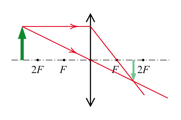
The image in a converging lens is reduced only when the source is located at a distance greater than twice the focal length. That is why, if you look through a magnifying glass at the “surrounding reality”, this reality will seem inverted and reduced.
Thus, d> 2f, its image will be reduced(real and inverted).
If we bring an object closer to the collecting lens, then its image will gradually grow and at the moment when the source is at twice the focal length, the image will become equal in size to the source itself.
As the source approaches further, its image will be enlarged and will become larger and larger until the object falls into the focal plane. In theory, at this moment the image becomes infinitely large and is infinitely far away.
Thus, when an object is at a distance f d f , its image is enlarged(real and inverted).
As the object approaches the lens further - after it passes through the focal plane - the image can no longer grow, since it is already infinitely large, and begins to shrink. At the same time, from the real it becomes imaginary, but still magnified. Only when the object reaches the main optical plane (the plane of the lens) does the image compare in size to the object.
Thus, when an object is at a distance d f, its image is enlarged(imaginary and direct).
- Orientation:
- Direct an image of an object is obtained when its orientation is preserved (the top remains up, in Right side- right). When constructing an image on a plane, the object and its image must be on one side of the main optical axis;
- Inverted; An image of an object is obtained when its orientation changes (up becomes down, right becomes left). When constructed on a plane, the object and its image must be on different sides of the main optical axis of the lens.
Diminished real
inverted image
Direct image in a converging lens - this is the image that can be observed, for example, using a magnifying glass. Such an image is obtained if the object is located between the plane of the lens (the main optical plane) and the focus (focal plane). In this case, the image appears enlarged. This is actually why a converging lens is often vulgarly called a magnifying glass.
So: A direct image of a point in a converging lens is obtained when the point is at a distance d f - between the main optical and focal planes- between the lens and focus. At the same time, it is enlarged and imaginary.
If an object is moved away from the lens at a distance greater than the focal length, the image is flipped and, accordingly, becomes inverted.
Thus, image at a distance d > f inverted(and real). It can be either reduced or increased (see above)
![]()
Enlarged real
inverted image
- "Reality":
- Valid the image is obtained in the lens if it is at the intersection of the rays emerging from the light source;
- Imaginary is obtained in a lens when it is not the rays themselves (the lines along which radiation energy propagates) that intersect, but the extensions of the rays;
A real image is, for example, an image of a film on a movie screen. Each point of the film is a point source of light, the image from which is the intersection point of the rays emanating from the source. When passing through a collecting lens The actual image is obtained when the object is at a distance greater than the focal one: d > f
. Moreover, it is always upside down and can be either larger or smaller in size than the original (see above).
A virtual image is obtained if the source is located closer to the lens than its focus: d f. In this case, rays emanating from any point cannot intersect when passing through the lens, but their extensions intersect.
When passing through a lens, rays can be refracted in various ways and depending on where the light source is located, its image may be characterized differently. For example, the image of an object that is located between the main focus and the main optical plane of a converging lens will appear direct, virtual and magnified. However, some combinations of image types cannot be obtained. For example, in a converging lens the real image is always inverted, but the virtual image is never reduced.
Ability to identify the types of images produced by lenses various types- one of the skills tested on the Unified State Exam
Exercise:
The interactive exercise consists of 8 parts, which require:- The ability to determine by the position of a point light source where the image is located;
- Determine the type of image obtained in a lens with positive optical power.
To complete the task, you must sequentially click on two corresponding elements of the picture or table.
Download exercise
The authors of interactive exercises marked with © CC-BY-SA are the persons indicated on the site. Interactive exercises are licensed Creative Commons Attribution-Share Alike 3.0
Attribution-ShareAlike (by-sa)- Attribution License - Copyleft. This license allows others to remix, revise, and build upon the work, even for commercial purposes, as long as attribution is given to the author and their derivative works are licensed under similar terms. This license is a copyleft license. All new works based on what is licensed under it will have a similar license, so all derivatives will be allowed to be modified and used for commercial purposes. When reproducing works distributed under this license, a link to the site is required!
Exercise updated 06/19/2013
Questions for self-control:
- What types of images can a converging lens produce?
- To size,
- By orientation,
- In terms of “reality”?
- Under what conditions will the image of an object be magnified?
- Can a magnifying glass produce a smaller image?
- In which case is the image and its source the same size?
- When is there no image in a converging lens and why?
- What is the difference between a real and virtual image of an object in an optical instrument?
- Is it possible to obtain a virtual and inverted image using one lens?


")


- Abstract: Elementary particles
- Presentation on the topic "management"
- History of the development of computer technology presentation for a lesson on the topic Historical development of computer technology presentation
- Astronomy Presentations Interesting Topics for Astronomy Presentations
- Presentation on history "counting years in history"
- Astronomy Presentations Astronomy Presentation Template
- The anniversary of the expulsion of the Karachais recalled the problem of rehabilitation of repressed peoples
- Udmurt people What peoples live on the territory of Udmurtia
- Russia is a multinational state We live in a multinational country
- The smallest peoples of the world Which group of peoples is the smallest
- How to change a cash receipt order in 1c
- Day of Remembrance of Fallen Russian Internal Affairs Officers Heroism of Police Officers
- Northern coast of Neva Bay
- Enviable beauties in politics (17 photos)
- The best ballet performances
- Biography, political activity
- The magical world of crystals
- How to salt milk mushrooms: a quick recipe
- Ten Surprisingly Profitable Illegal Trades
- Management project based on the example of an enterprise presentation