Training in electrical safety, labor protection, ecology, electrical safety, fire-technical minimum, first aid to victims of the courses
Topic 5. Methods and means of protection in electrical installations
Topic 5.2. Protective equipment in electrical installations
Instructions for the use and testing of protective equipment used in electrical installations
Basic terms.
|
Term |
Definition |
|
Personal protective equipment for the worker |
Protective equipment worn or used on a person's body or parts |
|
Basic electrical protective equipment |
An insulating electrical protective device, the insulation of which can withstand the operating voltage of an electrical installation for a long time and which allows you to work on live parts that are energized |
|
Additional electrical protective equipment |
An insulating electrical protective device, which by itself cannot provide protection against electric shock at a given voltage, but complements the main protection means, and also serves to protect against touch voltage and step voltage |
|
Touch voltage |
The voltage appearing on the human body when touching two points of the current circuit, including when the insulation between parts of electrical installations is damaged, which is simultaneously touched by a person |
|
Step voltage |
The voltage between two points of the ground or floor, caused by the spreading of the fault current into the ground, while simultaneously touching them with the feet of a person |
|
Safety sign |
A sign designed to warn a person about a possible danger, prohibit or prescribe certain actions, as well as for information about the location of objects, the use of which is associated with the exclusion or reduction of the consequences of exposure to hazardous and (or) harmful production factors |
|
Safety color |
A color designed to attract a person's attention to individual elements of production equipment and (or) building structures that can be sources of hazardous and (or) harmful production factors, fire extinguishing equipment and a safety sign |
|
Undistorted electric field strength |
The intensity of the electric field, not distorted by the presence of a person, determined in the zone where a person will be in the process of work |
|
Shielding device |
Collective protective equipment that reduces the strength of the electric field in the workplace |
|
Electric field influence area |
Space where the electric field strength with a frequency of 50 Hz is more than 5 kV / m |
|
Live work |
Work performed with touching live parts that are under operating voltage, or at distances to these live parts less than permissible |
|
Safe distance |
The smallest distance between a person and a source of a hazardous and harmful production factor, in which a person is outside the danger zone |
General Provisions
Electrical protective equipment includes:
- insulating rods of all types (operational, measuring, for applying grounding);
- voltage indicators of all types and voltage classes (with a gas-discharge lamp, contactless, pulse type, with an incandescent lamp, etc.);
- contactless voltage presence signaling devices;
- insulated tool;
- dielectric gloves, boots and galoshes, carpets, insulating coasters;
- protective fences (shields, screens, insulating linings, caps);
- portable grounding;
- devices and devices for ensuring labor safety during tests and measurements in electrical installations (voltage indicators for checking phase coincidence, devices for cable puncture, a device for determining the voltage difference in transit, cable damage indicators, etc.);
- safety posters and signs;
- other protective equipment, insulating devices and devices for repair work under voltage in electrical installations with a voltage of 110 kV and above, as well as in power grids up to 1000 V (polymer and flexible insulators; insulating ladders, ropes, inserts of telescopic towers and lifts; rods for transfer and leveling potential; flexible insulating coatings and linings, etc.).
Insulating electrical protective equipment is divided into basic and additional.
The main electrical protective equipment in electrical installations with voltages above 1000 V include:
- insulating rods of all types;
- insulating and electrical clamps;
- voltage indicators;
- devices and devices for ensuring labor safety during tests and measurements in electrical installations (voltage indicators for checking phase coincidence, devices for cable puncture, cable damage indicators, etc.)
- other protective equipment, insulating devices and devices for repair work under voltage in electrical installations with a voltage of 110 kV and above (polymer insulators, insulating stairs, etc.).
The main electrical protective equipment in electrical installations with voltages up to 1000 V includes:
- insulating rods;
- insulating and electrical clamps;
- voltage indicators;
- dielectric gloves;
- isolated tool.
Additional electrical protective equipment for work in electrical installations with voltages up to 1000 V includes:
- dielectric galoshes;
- dielectric carpets;
- insulating supports and pads;
- insulating caps.
Means of protection against electric fields of increased tension include individual shielding kits for work on the potential of the overhead line wire and on the ground potential in the switchgear and on the overhead line, as well as removable and portable shielding devices and safety posters.
The procedure for using protective equipment
Protective equipment should be kept as inventory in the premises of electrical installations (switchgears, power plant shops, at transformer substations, in distribution points of power grids, etc.) or included in the inventory of operational field teams, maintenance teams, mobile high-voltage laboratories, etc. .p., as well as issued for individual use.
Inventory means of protection are distributed between objects, operational-field teams in accordance with the system of organization of operation, local conditions and manning standards (Appendix 8).
Such a distribution with an indication of storage locations should be recorded in the lists approved by the chief engineer of the enterprise (head of the network area) or the person responsible for the electrical system.
The responsibility for the timely provision of personnel and the completion of electrical installations with tested protective equipment in accordance with the picking standards, the organization of proper storage and the creation of the necessary stock, the timely production of periodic inspections and tests, the withdrawal of unusable funds and the organization of their accounting are borne by the head of the shop, service, substation, network section , the foreman of the area in charge of electrical installations or workplaces, and in general for the enterprise - the chief engineer or the person responsible for the electrical system.
It is allowed, if necessary, to appoint, by written order, one person with an electrical safety group of at least IV, responsible for accounting, provision, organization of timely inspection, testing and storage of protective equipment in this unit.
Such an appointment does not replace the duties of foremen, who admit and manufacturers of works to, alongside control, the availability of the necessary protective equipment and their condition at the workplace.
If it is found that the protective equipment issued for a separate electrical installation is unsuitable, the personnel servicing it is obliged to immediately remove them, notify one of the above-listed persons about it, and make an entry in the logbook and the content of protective equipment (Appendix 1) or in the operational documentation.
Persons who have received protective equipment for individual use are responsible for their correct use and timely rejection.
Procedure for maintaining protective equipment
Protective equipment must be stored and transported in conditions that ensure their serviceability and suitability for use, therefore, they must be protected from moisture, contamination and mechanical damage.
Protective equipment must be stored in closed rooms. Rubber protective equipment in use should be stored in special cabinets, on racks, shelves, in boxes, etc. separate from the instrument. They must be protected from the effects of oils, gasoline, acids, alkalis and other substances that destroy rubber, as well as from direct exposure to sunlight and heat radiation from heating devices (no closer than 1 m from them). Protective equipment made of rubber in stock must be stored in a dry room at a temperature of 0-30 degrees. WITH.
Insulating rods and pliers are stored in conditions that prevent their sagging and contact with walls.
Special places for storing portable earthing should be numbered corresponding to those indicated on the portable earthing.
Gas masks must be stored in dry rooms in special bags.
Protective equipment is placed in specially designated places, as a rule, at the entrance to the premises, as well as on control panels. Storage areas should have a list of protective equipment. Storage areas should be equipped with hooks or brackets for rods, insulating pliers, portable grounding, posters and safety signs, as well as cabinets, racks, etc. for dielectric gloves, boots, galoshes, carpets, caps, insulating pads and supports, gloves, safety belts and ropes, goggles and masks, gas masks, voltage indicators, etc.
Protective equipment used by field crews and maintenance crews, mobile laboratories or in the personal use of personnel must be stored in boxes, bags or cases separately from other tools.
Protective equipment, isolating devices and devices for work under voltage should be kept in a dry, ventilated area.
Storage and transportation should be carried out under conditions that ensure their safety.
Shielding protective equipment should be stored separately from electrical protective equipment.
Individual shielding kits are stored in special cabinets: overalls - on hangers, and special footwear, head, face and hand protection - on shelves. During storage, they must be protected from moisture and corrosive environments.
Control over the state of protective equipment and their accounting
All electrical protective equipment and safety belts in operation must be numbered, with the exception of protective helmets, dielectric carpets, insulating supports, posters and safety signs, protective fences, transfer rods and potential equalization. The use of serial numbers is allowed.
The numbering procedure is established at the enterprise depending on the operating conditions of protective equipment.
The inventory number is applied directly to the protective equipment with paint or knocked out on metal (for example, on metal parts of a belt, an insulated tool, a rod, etc.), or on a special tag attached to the protective equipment (an insulating rope, etc.).
If the protective equipment consists of several parts, a common number for it must be put on each part.
In the subdivisions of enterprises and organizations of the industry and consumers of electricity, it is necessary to keep logs of accounting and the content of protective equipment. The presence and condition of protective equipment should be checked by inspection periodically, but at least 1 time in 6 months, by a person responsible for their condition, with a record of the results of the inspection in the journal. Protective equipment issued for individual use must also be registered in the journal.
Protective equipment, other than insulating supports, dielectric carpets, portable groundings, protective fences, posters and safety signs, received for use from manufacturers or warehouses should be checked against performance test standards.
The protective equipment that has passed the tests must be stamped.
The stamp must be clearly visible. It should be applied with indelible paint or glued to the insulating part near the stop ring of insulating electrical protective equipment and isolating devices for live work or at the edge of rubber products and guards. If the protective equipment consists of several parts, the stamp is placed on only one part.
On protective equipment that did not pass the test, the stamp must be crossed out with red paint.
The results of electrical and mechanical tests of protective equipment are recorded in a special log in the testing laboratory. In the presence of a large number of means of protection made of dielectric rubber, the results of their tests can be drawn up in a separate journal.
Protective equipment belonging to third parties is also stamped and, in addition, test reports are issued to the customer.
Insulated tools, voltage indicators up to 1000 V, as well as safety belts and safety ropes are allowed to be marked with accessible means with a record of the test results in the log book and the content of protective equipment.
Protective equipment received for individual use is also subject to testing within the time limits established by these Rules.
Rules for the use of protective equipment
Insulating electrical protective equipment should be used for their intended purpose in electrical installations with a voltage not higher than that for which they are designed (the highest allowable voltage), in strict accordance with these Rules.
The main and additional electrical protective equipment is designed for use in closed electrical installations, and in open electrical installations and on overhead power lines - only in dry weather. It is prohibited to use them in frost and precipitation. Outdoors in wet weather, only specially designed protective equipment designed to work in such conditions may be used.
Such protective equipment is manufactured, tested and used in accordance with technical conditions and instructions.
Before each use of the protective equipment, the personnel must check its serviceability, the absence of external damage, contamination, check the expiration date using the stamp.
It is prohibited to use protective equipment that has expired.
Rules for testing protective equipment
In operation, protective equipment is subjected to operational periodic and extraordinary tests (after repair, replacement of any parts, if there are signs of malfunction).
Extraordinary tests of protective equipment are carried out in accordance with the operational test standards. The operational test standards and their timing are given in Appendices 4 and 5.
Typical, periodic and acceptance tests are carried out at the manufacturer of protective equipment according to the standards given in Appendices 6 and 7.
During the tests, the mechanical and electrical characteristics of the protective equipment are checked.
Mechanical tests are carried out before electrical tests.
All electrical overvoltage testing of protective equipment must be carried out by specially trained persons.
Each protective device before the electrical test must be carefully examined in order to check the dimensions, serviceability of the completeness, the condition of the insulating surfaces, and the presence of the number. If the protective equipment does not comply with the requirements of these Rules, the test is not carried out until the detected deficiencies are eliminated.
Tests, as a rule, should be carried out with alternating current with a frequency of 50 Hz at a temperature of 15-35 degrees. WITH.
The rate of voltage rise to 1/3 of the test voltage can be arbitrary, further increase in voltage should be smooth and fast, but allowing the reading of the measuring device at a voltage of more than 3/4 of the test voltage. When the required value is reached, the voltage after the normalized time delay must be quickly reduced to zero or, at a value equal to 1/3 or less than the test value, it must be turned off (GOST 1516.2-76).
Testing of protective devices made of rubber can be carried out with direct (rectified) current. When tested with direct current, the test voltage shall be 2.5 times the value of the a.c. test voltage. The current flowing through the product is not standardized. The test duration is the same as with alternating current.
During the tests, an overvoltage is applied to the insulating part of the protective equipment. In the absence of a suitable voltage source necessary for testing the insulating electrical protective device as a whole, it is allowed to test it in parts. In this case, the insulating part of the protective equipment is divided into sections to which a part of the specified total test voltage is applied, proportional to the length and increased by 20%.
The main electrical protective equipment intended for electrical installations with voltages above 1 to 110 kV are tested with a voltage equal to 3 times the linear voltage, but not lower than 40 kV, and those intended for electrical installations with a voltage of 110 kV and above are tested with a voltage equal to 3 times the phase voltage. Additional electrical protective equipment is tested with a voltage that does not depend on the voltage of the electrical installation in which they are to be used, in accordance with the standards specified in Appendices 5 and 7.
The full test voltage is applied for 1 minute. for insulation made of porcelain and some types of non-hygroscopic materials (for example, fiberglass) and 5 min. for insulation made of solid organic materials (eg Bakelite).
For rubber insulation during operational tests, the duration of the test voltage is 1 min.
Breakdown, overlap and discharges along the surface are established according to the readings of measuring instruments and visually.
Currents flowing through products are standardized for voltage indicators up to 1000 V, rubber products and isolating devices for working under voltage.
Electrical protective equipment made of solid organic materials should be checked by feeling immediately after the test for the absence of local heating due to dielectric losses.
In the event of a breakdown, surface overlap, surface discharges, an increase in current through the product above the normalized value, the presence of local heating from dielectric losses, the protection means is rejected.
Technical requirements for certain types of protective equipment, standards
and the procedure for conducting tests, rules for using them
Electrical protective equipment
General Provisions
The insulating part of the electrical protective means from the side of the handle is limited by a ring or stop made of electrical insulating material.
For electrical protective equipment for electrical installations with voltages up to 1000 V (except for insulated tools), the height of the ring or stop must be at least 3 mm.
When using electrical protective equipment, do not touch their insulating part behind the stop ring or stop, as well as the working part.
Insulating parts of electrical protective equipment must be made of electrical insulating materials with stable dielectric properties (glass epoxy phenolic, paper-bakelite tubes, etc.). Materials that absorb moisture (paper-bakelite tubes, wood, etc.) must be coated with a moisture-crack-resistant varnish and have a smooth outer and inner surface without cracks, delamination and scratches.
The design of electrical protective equipment made of electrical insulating tubes must prevent the ingress of dust and moisture or provide for the cleaning of internal surfaces (for example, for vacuum booms).
The dimensions of the working part of the rods and voltage indicators are not standardized, however, they must be such that, when working with them in electrical installations, the possibility of an phase-to-phase short circuit or an earth fault is excluded.
In case of damage to the varnish coating (cracks, deep scratches) or other malfunctions of electrical protective equipment, they must be taken out of operation, repaired and tested. After drops and shocks, if necessary, voltage indicators are subjected to extraordinary tests.
In electrical installations with voltages above 1 kV up to 35 kV, use insulating rods (except for measuring ones), portable grounding, vacuum cleaner rods, voltage indicators and insulating and electrical measuring pliers should be in dielectric gloves. The use of gloves in electrical installations of 110 kV and above is determined by safety regulations and local conditions.
The use of dielectric gloves is not required when working on the measuring rods.
Insulating pliers.
Purpose and design of pliers
Insulating pliers are intended for replacing fuses in electrical installations up to and above 1000 V, as well as for removing fences, linings and other similar work in electrical installations up to 35 kV.
The pliers consist of a working (pliers jaws), insulating parts and a handle (s).
The insulating part and the handle are made of electrical insulating material (for example, polypropylene - tongs up to 1000 V, glass epoxyphenol or paper-bakelite tubes - tongs up to 35 kV, etc.).
The working part is made of both electrical insulating material (tongs up to 1000 V) and metal. Rubber oil-resistant tubes should be put on the metal sponges to prevent damage to the porcelain of the fuse holder.
The insulating part of the pliers must be separated from the handle by limit stops (ring).
The sizes of the ticks are given in table. 7.
Minimum dimensions of insulating pliers
Table 7.
|
Rated voltage of the electrical installation, kV |
Length, mm |
|
|
insulating part |
handles |
|
|
Up to 1 inclusive |
Not standardized, determined by ease of use |
|
|
6 to 10 inclusive |
||
|
Over 10 to 35 inclusive |
||
The mass of ticks should ensure the ability to conveniently work with one person.
Tick test
In operation, mechanical tests of the tongs are not carried out.
Electrical tests
Tests of clamps for voltages up to 1000 V for dielectric strength during operational tests should be carried out by applying a test voltage of 2 kV for 5 minutes. between the metal clamps applied to the handles (behind the stop projections) from the side of the insulating part and to the jaws at the base of the oval cutout.
Checking the electrical strength of the clamps for voltages of 6-10 and 35 kV during operational tests is carried out by applying a test voltage equal to 3 times linear, but not less than 40 kV and 105 kV, respectively, for 5 minutes. to the working part and the temporary electrode, imposed at the restricting ring from the side of the insulating part.
Terms of use of ticks
Clamps for voltages up to 1 kV when using them must be held on an outstretched hand, away from live parts, and clamps for voltages above 1 kV - only by the handle, it is forbidden to touch their insulating part.
Voltage indicators up to 1000 V.
Purpose and design
To check the presence or absence of voltage in electrical installations up to 1000 V, two types of indicators are used: two-pole, operating with an active current flowing, and single-pole, operating with a capacitive current.
Two-pole pointers are designed for AC and DC electrical installations, and single-pole - for AC electrical installations.
The use of test lamps for checking the absence of voltage is FORBIDDEN due to the danger of their explosion when the lamp is turned on for 220 V and line voltage of 380 V.
Two-pole indicators consist of two cases containing electrical circuit elements. The elements of the electrical circuit are interconnected by a flexible wire that does not lose its elasticity at negative temperatures, with a length of at least 1 m. At the points of entry into the housing, the connecting wire has shock-absorbing bushings or thickened insulation.
The single-pole indicator is housed in one housing.
The electrical circuit of a two-pole voltage indicator should contain lug contacts and elements that provide visual, acoustic or visual-acoustic indication of voltage. Visual and acoustic signals should be continuous or intermittent.
The electrical circuit of a two-pole indicator with visual indication can contain a pointer-type device or a digital sign-synthesizing system (with a small-sized power supply for the indicating scale). Pointers of this type can be used for voltages from 0 to 1000 V.
The electrical circuit of a single-pole voltage indicator should contain an indication element with an additional resistor, a tip contact and a contact on the end (side) part of the case, with which the operator's hand comes into contact.
The length of the uninsulated part of the contact lugs must not exceed 5 mm. The lug contacts must be rigidly fixed and must not move along the axis.
Tests of voltage indicators
In operation, mechanical tests of pointers are not carried out.
Electrical tests
Operational tests of voltage indicators up to 1000 V consist in determining the indication voltage, checking the circuit with increased voltage, measuring the current flowing through the indicator at the highest operating voltage, and testing insulation with increased voltage.
To check the indication voltage for a two-pole indicator, the voltage from the test setup is applied to the tip contacts, for a single-pole indicator - to the tip contact and the contact on the end (side) part of the case. The indication voltage of voltage indicators up to 1000 V should be no higher than 90 V.
To check the circuit for a two-pole indicator, the voltage from the test setup is applied to the tip contacts, for a single-pole indicator - to the tip contact and the contact on the end (side) part. The test voltage when checking the circuit must exceed the highest value of the operating voltage by at least 10%. Test duration - 1 min.
The value of the current flowing through the pointer at the highest value of the operating voltage should not exceed:
- 0.6 mA for a single-pole voltage indicator;
- 10 mA for a two-pole voltage indicator with elements providing visual or visual-acoustic signal indication;
- for voltage indicators with an incandescent lamp up to 10 W and 220 V, the current value is determined by the lamp power. The current value is measured using an ammeter connected in series with the pointer.
To test the insulation of voltage indicators with increased voltage at two-pole indicators, both insulating bodies are wrapped in foil, and the connecting wire is lowered into a grounded vessel so that water covers the wire, not reaching the handle by 9-10 mm. One wire from the test setup is connected to the lug contacts, the second, grounded, to the foil and immersed in water (Fig. 10).
Rice. ten. Schematic diagram of dielectric strength test
handles and voltage indicator wires
1 - test pointer; 2 - test transformer; 3 - bath with water; 4 - electrode
For single-pole voltage indicators, the insulating body is wrapped with foil along its entire length up to the limit stop. A gap of at least 10 mm is left between the foil and the contact on the end part of the case. One wire from the test setup is connected to the lug contact, the other, grounded, to the foil.
It is recommended to carry out the tests on a dielectric gloves, boots and galoshes testing machine (fig. 2.4). The insulation of voltage indicators up to 500 V must withstand a voltage of 1 kV, and of voltage indicators above 500 V - 2 kV. Test duration - 1 min.
Guidelines for using pointers
Single-pole indicators are recommended to be used when checking secondary switching circuits, determining the phase conductor when connecting electric meters, holders, switches, fuses, etc. It should be remembered that when checking for the presence or absence of voltage, the signal lamp may glow from the induced voltage.
Before use, the indicator is checked for good condition on live parts that are known to be energized.
When using single-pole voltage indicators, in order to avoid their incorrect indication, the use of dielectric gloves is prohibited.
Devices and devices for ensuring labor safety
when carrying out tests and measurements in electrical installations.
Electric clamp meter.
Purpose and design
Clamps are designed to measure current, voltage and power in electrical circuits up to 10 kV without breaking their integrity.
The principle of operation of the clamp is that the current is measured by a transformer, the secondary winding of which is closed to the measuring circuit. The primary winding is a bus or wire with the measured current.
Pliers for work in electrical installations up to 10 kV consist of a working, insulating part and a handle.
The working part consists of a detachable magnetic circuit, a winding and a removable or built-in measuring device. The body of the measuring device is plastic. The magnetic circuit is made of sheet electrical steel.
The insulating part with the stop and the handle must be made of electrical insulating material. The minimum length of the insulating part is 380 mm and the handle is 130 mm.
All individual parts of the pliers must be firmly and securely fastened together.
Pliers for electrical installations up to 1000 V consist of a working part (a detachable magnetic circuit, a winding and a measuring mechanism) and a housing, which is at the same time an insulating part with a stop and a handle.
Tick testing
Clamps for electrical installations up to 1000 V are tested for 5 min. voltage of 2 kV.
When testing the clamp, voltage is applied to the magnetic conductor and foil electrodes or wire ties at the stop ring from the side of the insulating part (for clamp up to 10 kV) or at the base of the handle (for clamp up to 1000 V).
Terms of use of ticks
When using clamps for measurements in circuits above 1000 V, it is forbidden to use remote devices, as well as switch the measurement limits without removing the clamps from live parts. When measuring, the pliers should be held by weight.
In this case, it is forbidden to lean towards the meter to read the readings. It is necessary to work with clamps up to 10 kV with dielectric gloves.
It is forbidden to work with clamps up to 1000 V, being on the overhead line support.
Cable piercing devices
In addition to the listed devices, when working in electrical installations, various types of safe devices for cable puncture are used: remote puncture devices with a manual mechanical drive or electric drive and pyrotechnic cable puncture devices.
Purpose and design of devices
Devices for cable puncture are designed to indicate the absence of voltage on the repaired cable up to 10 kV before cutting it by puncturing the cable in diameter and short-circuiting all cores of different phases to each other and to the ground.
The devices include a working body, a grounding device, an insulating rod, a reducer or electric drive with an insulating insert, or a trigger device consisting of a cord and an insulating rod.
The grounding device includes a grounding rod with a grounding rope or clamps.
The design of the device should ensure its reliable fastening to the cable to be pierced and automatically orient the axis of the cutting (piercing) element with the diameter of the pierced cable of any cross-section, and also provide for a blocking that excludes a shot when the shutter is not closed and the device is pyrotechnic.
A mechanical-type device should pierce the cable in diameter for at least 180 movements, while the maximum force should not exceed 29.4 N. The remote puncture device should pierce the cable for no more than 5 minutes. The pyrotechnic device should pierce the cable in one shot.
The length of the insulating part of the device must be at least 230 mm. The length of the drive cord (connecting cable) must be at least 10 m. The cross-section of the grounding cable must be at least 25 mm.
Electrical tests
During operational tests, the insulating parts of the devices (the insulating rod or the insulating insert of the electric drive) are tested with an increased voltage of 40 kV for 5 minutes.
The test voltage is applied to the insulating part of the rod or to the metal flange of the actuator and a special terminal.
Terms of use of devices
The cable is punctured by two specially trained persons, one of whom is the supervisor.
When piercing the cable, use dielectric gloves and protective goggles, while standing on an insulating base on top of the trench as far as possible from the cable to be pierced.
When working with the device, it is necessary to observe the safety measures set forth in the operating instructions. Daily and periodic maintenance is also performed in accordance with the requirements of the operating instructions.
Dielectric rubber protectors.
Dielectric rubber gloves.
Purpose and requirements for them
Gloves are designed to protect hands from electric shock when working in electrical installations up to 1000 V as the main electrical protective equipment, and in electrical installations above 1000 V - as an additional one.
In electrical installations, it is allowed to use only gloves marked for the protective properties En, Ev, (En - for protection against electric current with voltage up to 1000 V, Ev - for protection against electric current with voltage above 1000 V).
The length of the gloves must be at least 350 mm. The size of the gloves should allow woolen or cotton gloves to be worn under them to protect hands from low temperatures when servicing open devices in cold weather. The width along the lower edge of the gloves should allow them to be pulled over the sleeves of outerwear. Gloves can be five-fingered or two-fingered.
Glove testing
In operation, only electrical tests are carried out on gloves.
Once every 6 months. Gloves must be tested with an increased voltage of 6 kV for 1 minute, the current through the glove should not exceed 6 mA. During the test, dielectric gloves are immersed in a metal vessel with water at a temperature of 25 + -10 degrees. C, which is also poured into these products. The water level both outside and inside the products should be 50 mm below the top edge of the gloves.
The protruding edges of the gloves must be dry. One terminal of the test transformer is connected to the vessel, the other is grounded. An electrode is lowered inside the gloves, connected to ground through a milliammeter. One of the possible test setup schemes is shown in Fig. 11. During the test, switch "P" is first set to position A in order to determine the absence or presence of breakdown by the signal lamps. In the absence of breakdown, the switch is set to position B to measure the current passing through the glove. The product is rejected if the current passing through it exceeds the norm or sharp fluctuations of the milliammeter needle occur.
In the event of a breakdown, turn off the defective product or the entire installation.
At the end of the tests, the products are dried.
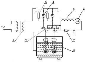
Rice. eleven. Schematic diagram of testing dielectric gloves, bot and galoshes
1 - test transformer; 2 - changeover contacts;
3 - shunt resistance (15-20 kOhm); 4 - gas discharge lamp;
5 - throttle; 6 - milliammeter; 7 - spark gap; 8 - bath with water
Terms of use of gloves
When using gloves, care should be taken to ensure that they are not wet or damaged.
Before using gloves, check for punctures by twisting them towards the fingers.
When working with gloves, their edges must not be rolled up.
To protect against mechanical damage, it is allowed to wear leather or canvas gloves or mittens over the gloves.
Gloves in use should be periodically (according to local conditions) disinfected with soda or soapy water.
Special dielectric footwear made of polymer materials.
Dielectric rubber boots, galoshes. Purpose and requirements for them
Special dielectric shoes (glued galoshes, rubber glued or molded boots, including boots in tropical design) are an additional electrical protective device when working in closed, and in the absence of precipitation - in open electrical installations.
In addition, dielectric boots and galoshes protect workers from stride voltage.
Shoes are used: galoshes - at voltages up to 1000 V; bots - at all voltages.
According to their protective properties, footwear is designated as: En - glued rubber galoshes; EV - rubber glued and molded boots.
Dielectric shoes should be different in color from the rest of the rubber shoes.
Overshoes and boots consist of a rubber upper, rubber grooved sole, textile lining and internal reinforcements.
Bots must have cuffs. Shaped bots can be produced without lining.
The height of the bot must be at least 160 mm.
Dielectric Shoe Testing
In operation, dielectric galoshes are tested with a voltage of 3.5 kV, and boots - with a voltage of 15 kV for 1 min.
The currents flowing through the product should be no more than 2 mA for galoshes and 7.5 mA for bot.
The tests are carried out on the installation shown in Fig. eleven.
During tests, the water level both outside and inside horizontally installed products should be 20 mm below the sides of the overshoes and 50 mm below the edge of the deflated cuffs of the boat.
Rules for the use of dielectric shoes
Electrical installations should be equipped with dielectric footwear of several sizes.
Before use, galoshes and boots should be inspected in order to detect defects (delamination of facing parts, looseness of the lining on the insole, divergence of the ends of the lining, foreign hard inclusions, sulfur protrusion).
Dielectric rubber carpets and insulating supports.
Purpose and requirements for them
Dielectric rubber carpets and insulating stands are used as additional electrical protective equipment in electrical installations up to and above 1000 V.
Carpets are used in closed electrical installations of all voltages, except for particularly damp rooms, and in open electrical installations in dry weather.
The stands are used in damp and contaminated rooms.
Carpets are made in accordance with the requirements of GOST 4997-75, depending on the purpose and operating conditions of the following two groups: 1st group - normal execution and 2nd group - oil and petrol resistant.
Carpets must have a grooved face and be of one color.
The insulating base consists of a deck, fixed on support insulators with a height of at least 70 mm. It is recommended to use insulators of the SN-6 type, produced specifically for the manufacture of stands.
A flooring of at least 500x500 mm in size should be made of wood planks without knots and oblique layers, carved from well-dried wood. The gaps between the planks should not exceed 30 mm. Solid decks are not recommended as they make it difficult to verify that the insulators are not accidentally bridged. The flooring must be painted on all sides.
Insulation pads must be strong and stable. In the case of using removable insulators, their connection to the flooring must exclude the possibility of the flooring sliding off. To eliminate the possibility of the insulating support overturning, the edges of the flooring should not protrude beyond the supporting surface of the insulators.
Testing carpets and coasters
In use, carpets and coasters are not tested. They are discarded during inspections. Carpets should be cleaned of dirt and inspected at least once every 6 months. If defects are found in the form of punctures, tears, cracks, etc. they should be replaced with new ones.
The stands are inspected once every 3 years for the absence of violations of the integrity of the support insulators, kinks, weakening of the connection between the individual parts of the flooring. If these defects are found, they are rejected, and after the elimination of the defects, they are tested according to the standards of acceptance tests.
Rules for the use of carpets and stands
After storage at negative temperatures, carpets must be kept packed at a temperature of 2 + -5 degrees before use. From at least 24 hours
Carpets and insulating pads must be cleaned of dirt, dried and inspected for defects before use.
Protective fences
Protective fences are used to prevent accidental approach and touch to live parts that are energized and located near the work site.
Protective fences can be of the following types: shields (screens); insulating pads; insulating caps.
Shields (screens).
Purpose and design
Shields, screens are used for temporary fencing of live parts that are energized up to and above 1000 V.
Shields should be made of dry wood, impregnated with linseed oil and painted with colorless varnish, or from durable electrical insulating material without the use of metal fasteners.
The surface of the boards can be solid (to protect workers from accidental approach to live parts that are energized) or lattice (to fence the entrance to cells, chambers, walkways, etc.).
The design of the shield should be durable and comfortable, excluding the possibility of warping and overturning, and the mass is such that one person can carry it. The height of the backboard must be at least 1.7 m, and the distance from the bottom edge to the floor must be no more than 10 cm.
Shield tests
Mechanical and electrical tests of boards are not carried out; their suitability for use is determined by inspection.
During inspections, the shields should check the strength of the connection of parts, their stability and the strength of parts intended for reliable installation or fastening of shields, the presence of posters and safety signs.
Rules for the use of shields
Contact of shields with live parts that are energized is not allowed. The distance from the shields enclosing the workplace to live parts that are energized must be maintained in accordance with the requirements of safety regulations. In electrical installations with a voltage of 6-10 kV, this distance, if necessary, can be reduced to 0.35 m.
On the boards, warning posters "STOP! VOLTAGE" or appropriate inscriptions must be affixed.
Boards should be installed reliably, but they should not prevent personnel from leaving the premises in case of danger.
It is forbidden to remove or rearrange the fences installed during the preparation of workplaces until the end of the work.
Insulating pads.
Purpose and design
Insulating linings are used in electrical installations up to 20 kV to prevent accidental contact with live parts in cases where it is not possible to shield the workplace with shields. In electrical installations up to 1000 V, overlays are also used to prevent erroneous switching on of circuit breakers.
The pads should be made of durable electrical insulating material. Their design and dimensions must be such that the live parts are completely closed.
In electrical installations up to 20 kV, rigid linings made of solid electrical insulating material (fiberglass, getinax, etc.) are used.
In electrical installations up to 1000 V, flexible dielectric rubber pads can be used to cover live parts during work without removing the voltage.
Insulation pad testing
Mechanical tests of insulating linings in operation are not carried out.
For the dielectric strength test, a rigid insulating strip is first placed between two plate electrodes, the edges of which should not reach the edges of the strip by 50 mm, then on each side between the electrodes, the distance between which should not exceed the distance between the poles of the disconnector for the corresponding voltage.
Dielectric rubber pads for electrical installations up to 500 V are tested with a voltage of 1 kV, over 500 to 1000 V - 2 kV for 1 min. A strip with a corrugated surface moistened with water (in the presence of corrugation) is placed between two electrodes, the edges of which should not reach the edges of the strip by 15 mm. To measure the current flowing through the pad, a milliammeter is included in the transformer step-up winding circuit. The operational test current should not exceed 6 mA. Test duration - 1 min.
Rigid linings for electrical installations up to 1000 V are tested according to the same standards as rubber, but without measuring the current through the product.
Terms of use of overlays
Installation of overlays on live parts with voltages above 1000 V should be carried out by two persons using dielectric gloves and insulating rods or pliers.
Before use, the pads should be cleaned of contamination and checked for cracks, violations of the varnish, tears and other damage. The pads should be protected from moisture and dirt.
Insulating caps
Purpose and design
Insulating caps are intended for use in electrical installations up to 10 kV, the design of which, according to electrical safety conditions, excludes the possibility of applying portable groundings during repairs, tests and determining the locations of damage.
Caps for electrical installations up to 10 kV are made of the following types:
- for installation on the veins of disconnected cables located near live parts that are under operating voltage;
- for installation on disconnected blades of single-pole disconnectors on assemblies with vertical phase arrangement;
- for installation on single-pole and three-pole disconnectors.
The design of the caps provides for the installation of a clamp on the front side to fix the cap on the pin of the operating rod during its installation.
The hoods are made of dielectric rubber, plastic, fiberglass or other insulating materials with stable dielectric properties.
Cap tests
In operation, the caps for installation on the veins of disconnected cables should be tested once every 12 months, with a voltage of 20 kV for 1 min., And the caps for installation on disconnected disconnector blades must be tested once every 12 months. are inspected for cracks, tears and other damage. The test procedure for caps is the same as for dielectric gloves.
Terms of use of caps
Before installing the hoods, the absence of voltage on the cable cores and disconnector blades must be checked.
Installation (removal) of the caps is carried out by two persons using dielectric gloves, an operating rod and a dielectric carpet or an insulating support. The sequence of caps installation from bottom to top, removal - from top to bottom.
Isolated tool.
Purpose and requirements for the tool
An insulated tool includes a fitting and assembly tool with insulating handles (adjustable wrenches, ratchet wrenches; pliers, pliers; side and socket nippers; screwdrivers, fixed knives, etc.), used for working under voltage in electrical installations up to 1000 V as the main electrical protective equipment.
It is allowed to use insulated tools manufactured in accordance with the requirements of GOST 1156-79 (with single-layer insulation) and publication IEC 900 (1987) (with multi-layer insulation).
Insulating handles should be made in the form of dielectric covers, fitted on the handles of the tool, or a non-removable single-layer or multi-layer coating made of moisture-resistant, oil-resistant, non-fragile electrical insulating material, applied by injection molding, dipping, etc. The surface of the insulating coating must not be slippery. The shape and grooves of the surface of the insulating handles should ensure ease of use of the tool.
The connection of the insulating handles with the handles of the tool and the insulation of the screwdriver rods must be strong, excluding the possibility of their mutual longitudinal movement and rotation during operation.
The insulation must cover the entire handle and be at least 100 mm long to the middle of the stop. The stop must have a height of at least 10 mm, a thickness of at least 3 mm and must not have sharp edges and edges. The height of the stop of the screwdriver handles is at least 5 mm.
The thickness of multi-layer insulation should not exceed 2 mm, single-layer - 1 mm. The insulation of the screwdriver shafts must not have stops. The insulation of the screwdriver shafts should end no more than 10 mm from the end of the screwdriver blade.
Each layer of a multi-layer insulation coating must have a different color.
Tool testing
In operation, mechanical testing of the tool is not carried out.
Electrical tests
A tool with single-layer insulation in operation is tested with a voltage of 2 kV for 1 min.
To carry out electrical tests, the instrument, previously cleaned of dirt and grease, is immersed with the insulated part in a bath of water so that the water does not reach the edge of the insulation for 10 minutes. One terminal of the test transformer is connected to the metal part of the instrument, and the other, grounded, is connected to a bath of water. The test can be carried out on a dielectric glove testing machine.
Tools with multilayer insulation are inspected in service. If the coating consists of two layers, then when a different color appears from under the top layer, the tool must be replaced.
If the coating consists of three layers, then if the top layer is damaged, the tool can be left in operation. If a lower layer of insulation appears, the tool must be immediately taken out of service.
Instrument usage rules
The instrument must be inspected before each use. The insulating handles of the tool should not have cavities, cracks, chips, swellings and other defects that lead to a deterioration in appearance and a decrease in mechanical and electrical strength.
During storage and transportation, the instrument must be protected from moisture and contamination.
Safety Posters and Signs
Purpose and execution
Safety posters and signs should be used to prohibit actions with switching devices, which, if turned on by mistake, may energize the place of work; movement without protective equipment in outdoor switchgears of 330 kV and above with an electric field strength above 15 kV / m (prohibiting posters); to warn of the danger of approaching live parts that are energized (warning posters and signs); to permit certain actions only when specific labor safety requirements are met (prescriptive posters); to indicate the location of various objects and devices (directional posters).
Permanent posters and signs are recommended to be made of electrical insulating materials (fiberglass, polystyrene, getinax, textolite, etc.), and on concrete and metal surfaces (overhead line supports, cell doors, etc.) - to be applied with paints using stencils. Portable posters and signs are made of electrical insulating materials. For electrical installations with open current-carrying parts, it is not allowed to use portable posters made of conductive material. Installation of permanent and portable posters and signs made of metal is allowed only away from live parts.
Log book and maintenance of protective equipment
|
Name of protective equipment, type) |
|||||||||
|
Test date |
date |
date |
Result |
Signature |
A place |
date |
Signature |
Example- |
|
Notes:
1. Periodic examinations are carried out at least once every 6 months.
2. When issuing a test report to third-party organizations, the report number is indicated in the "Note" column.
3. All protective equipment must be inspected before use, regardless of the timing of periodic inspections.
4. Dielectric carpets in operation are inspected once every 6 months, insulating stands - once every 36 months, insulating caps for disconnected disconnector blades - once every 12 months.
Norms of completing by means of protection
|
Switchgears with voltages up to 1000 V in power plants, substations and located in various industrial premises |
|
|
Isolating rod (operative or universal) |
According to local conditions |
|
Voltage indicator |
|
|
Insulating pliers |
|
|
Dielectric Gloves |
|
|
Dielectric galoshes |
|
|
Dielectric carpet or insulating pad |
According to local conditions |
|
Safety fences, insulating pads, portable posters and safety signs |
|
|
Protective glasses |
|
|
Portable grounding |
According to local conditions |
Notes:
1. Picking rates are minimum and mandatory. Chief engineers are given the right, depending on local conditions (layout and voltage of electrical installations, the service sector of operating and maintenance personnel and their number in a shift or team, etc.), to increase their number and supplement the nomenclature.
2. When placing switchgear equipment of the same voltage (above or up to 1000 V) on different floors or in several rooms, separated from each other by doors or other rooms, the specified number of protective equipment applies to the entire switchgear as a whole.
3. Switchgears of the same voltage, with no more than four of them, located within one building (power plants, workshops of an enterprise) and serviced by the same personnel, can be provided with one set of protective equipment (excluding protective fences and portable grounding).
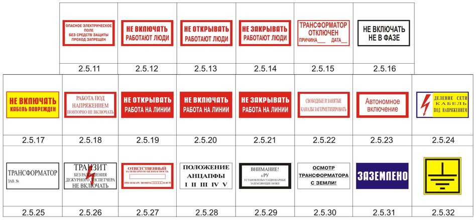
Safety Posters and Signs
|
Poster or sign number, purpose and name |
Application area |
|
1. To prohibit the supply of voltage to the workplace: DO NOT TURN ON! PEOPLE WORK |
In electrical installations up to and above 1000V. It is hung on the drives of disconnectors, isolators and load break switches, on keys and buttons of remote control, on switching equipment up to 1000 V (automatic machines, circuit breakers, switches), if they are turned on by mistake, voltage can be applied to the workplace. On connections up to 1000V, which do not have switching devices in the circuit, the poster is hung up at the removed fuses |
|
2. To prohibit the supply of voltage to the line on which people work: DO NOT TURN ON! WORK ON THE LINE |
The same, but hung out on the drives, keys and control buttons of those switching devices, if they are turned on by mistake, voltage can be applied to the overhead or cable line on which people work |
|
3. To warn about the danger of the impact of electronic signals on personnel and to prohibit movement without protective equipment: HAZARDOUS ELECTRIC FIELD WITHOUT PROTECTION EQUIPMENT. NO ENTRY |
In outdoor switchgear with a voltage of 330 kV and above. It is installed after measuring the EF strength at a height of 1.8 m from the level of the planning on the fences of the sections where the EF level is higher than 15 kV / m: on the routes bypassing the outdoor switchgear; outside the routes of bypassing the outdoor switchgear, but in places where it is possible for personnel to stay while performing other work (for example, under a low sagging busbar of equipment or a bus system) The poster can be mounted on a specially designed pole with a height of 1.5-2 m |
|
4. To prohibit the supply of compressed air, gas: DON `T OPEN, PEOPLE WORK |
In electrical installations of power plants and substations. They are hung on the valves and valves of air ducts to the air collectors and pneumatic drives of switches and disconnectors, in the event of an erroneous opening of which, compressed air can be supplied to working people or a switch or disconnector on which people work can be activated; hydrogen, carbon dioxide and other pipelines, if mistakenly opened, there may be a danger to working people |
|
5. To prohibit repeated manual switching on of overhead line switches after their automatic Shutdown poster without portable approval from the work manufacturer: WORK UNDER VOLTAGE. DO NOT RETURN ON |
On the control keys of the switches of the overhead line being repaired during work under voltage |
|
6. To alert you to the danger of electric shock: |
In electrical installations up to and above 1000V in power plants and substations. It is reinforced on the outside of the switchgear entrance doors, with the exception of the switchgear and KTP doors located in these devices; external doors of chambers of switches and transformers; fences for live parts located in production facilities, switchboard doors and assemblies with voltages up to 1000V |
|
In populated areas, it is strengthened on supports of overhead lines above 1000 V at a height of 2.5-3 m from the ground, with spans less than 100 m, it is strengthened through a support, with spans of more than 100 m and crossings over roads - at each support. When crossing roads, signs should be facing the road, in other cases - on the side of the support alternately on the right and left sides. Posters are mounted on metal and wood supports |
|
|
7. To alert you to the danger of electric shock: CAREFULLY! ELECTRIC VOLTAGE |
On reinforced concrete supports of overhead lines |
|
8. To alert you to the danger of electric shock: STAY! VOLTAGE |
In electrical installations up to and above 1000 V in power plants and substations. In the closed switchgear, they are hung on temporary protective fences of current-carrying parts that are under operating voltage (when the permanent fence is removed); on temporary fences installed in passages where you should not enter; on permanent enclosures of cameras adjacent to the workplace. In the outdoor switchgear, they are hung out during work performed from the ground, on ropes and cords that enclose the workplace; on structures near the workplace on the way to the nearest live parts that are energized |
|
9. To warn of the danger of electric shock during high voltage tests: TRIAL LIFE THREATENING |
Hang out with an inscription outward on equipment and fences of live parts or preparation of a workplace for testing with increased voltage |
|
10. To warn of the danger of lifting in which it is possible to approach live parts that are energized: DO NOT GET IN! KILL! |
In RU, they are hung on structures adjacent to the one intended for lifting personnel to a workplace located at a height along the structures, |
|
11. To indicate the workplace: WORK HERE |
In electrical installations of power plants and substations. Hang out in the workplace. In the outdoor switchgear, in the presence of protective fences of the workplace, they are hung out in the place of passage behind the fence |
|
12. To indicate a safe lifting path to a work station located at a height: CLICK HERE |
Hang out on structures or stationary ladders, along which it is allowed to climb to a workplace located at a height |
|
13. To indicate the inadmissibility of supplying voltage to the grounded section of the electrical installation: EARTHED |
In electrical installations of power plants and substations. They are hung on the drives of disconnectors, separators and load break switches, in case of erroneous switching on of which voltage can be applied to the grounded section of the electrical installation and on the keys and buttons of the remote control |
Notes:
1. In electrical installations with large-sized equipment, the dimensions of the posters are allowed to be increased in the ratio of 2: 1, 4: 1, 6: 1 to the dimensions indicated in the table.
Control questions:
1. How are the results of electrical tests of protective equipment formalized?
2. What is the length of handle insulation for insulated tools?
3. When should a protective device be subjected to an extraordinary test?
4. What should the organization's personnel do before each use of protective equipment?
5. How can you determine that a protective device has failed electrical tests?
6. What are the requirements for stamping the tested protective equipment?


- Rules for the use of electrical protective equipment when carrying out work in electrical installations
- How to sew fleece mittens
- Protective equipment in electrical installations
- Computer glasses: which is better to choose
- How to wash clothes with Thinsulate insulation
- Training in electrical safety, labor protection, ecology, electrical safety, fire-technical minimum, first aid to victims of the courses
- Protective equipment in electrical installations up to and above 1000 Volts
- What is fleece fabric, where is it used and how to care for it
- Personal protective equipment
- What is this fabric?
- Thinsulate
- "From the" Royal Circus "by Gia Eradze
- Drugs, longing for a friend, or murder
- Taisiya Povaliy (Giryavets) - biography, personal life and discography of the Ukrainian singer
- Viktoria karaseva's relatives are worried about the fact that she stopped leaving Tori's house from house 2 now
- Brief biography of Glinka What oppressed Glinka
- Biography and personal life of Maria Sittel Life of Maria Sittel
- T-Killah: nobody ever left me Alexander Tarasov got married
- Unknown facts about famous writers
- Maxim Gorky: biography, personal life M bitter direction